
Abstract on the topic of final work The control system of the speed modes of the reversible rolling mill
Content
- Introduction
- 1. Relevance of the topic
- 2. Rolling mill overview
- 2.1. Rolling production. General definitions and concepts.
- 2.2. Rolling process classification
- 2.2.1. Longitudinal rolling
- 2.2.2. Cross rolling
- 2.2.3. Cross–helical rolling
- 2.3. Rolling mill
- 2.3.1. Classification and device rolling mills
- 3. Automation of the rolling process.
- List of sources
Introduction
Reversible rolling mills are high-performance metallurgical aggregates that determine the efficiency of the entire hot-rolling process chain until the finished product is produced. In this regard, their control systems must ensure high performance and operational reliability of electrical and mechanical equipment.
The automated control system for the rolling process on the section of the reversing mill includes three interconnected and structurally coordinated subsystems that perform information and control functions. This does not aim to provide full automatic control of the site without operator participation, which is explained by the peculiarities of the technology and the design of mechanisms that require visual monitoring of the correctness of operations and changes in management strategy depending on situations arising in the management process.
The tasks of automation include the implementation of individual operations that ensure compliance with rolling technology, improving the working conditions of the operator and preventing the occurrence of emergency modes. For example, an automated speed control system (ACS CP) performs the functions of joint control of rolling, working roller tables and the main drive with speed matching when using one master device (commander controller). Submission and capture of metal are carried out at a reduced capture rate. This is followed by an automatic increase in the speed of the main drive to the value specified by the rolling program, and then decrease to the ejection speed (this calculates the current value of the non-rolled part of the workpiece using photo sensors for the position of the end of the workpiece and a pulse sensor installed on the roll drive).
The automated control system of the pressure device (ACS NU) provides automatic installation of the upper roll in accordance with a given rolling program when counting the number of passes.
1. Relevance of the topic
The object of the study is the control system of the reversing rolling mill. With the development of computer technology, it is possible to increase the production and operational reliability of high-performance metallurgical units and equipment. Information support of the production process is improved, for example, continuous monitoring of all rolling parameters is provided. To implement such functions, both specialized devices and universal logic controllers are used. In the master's work, an example of the implementation of a speed control system for a reverse rolling mill based on a programmable logic controller VIPA is considered. The relevance of the topic is also due to the fact that during the modernization, as a rule, there is a transition from analogue to discrete control systems. This requires preliminary design work to ensure maximum efficiency.
2. Overview of rolling production
2.1. Rolling production. General definitions and concepts.
Rolling & ndash; the process of plastic deformation of bodies on a rolling mill between rotating drive
rolls (part of the rolls may be non-driven). The words driven rollers
mean that the energy required
to effect the deformation, it is transmitted through rolls connected to the rolling mill engine. Deformable
the body can also be pulled through non-driven (idle) rolls, but this will not be a rolling process, but a drawing process.
Rolling is one of the main methods of metal forming. Rolling receive products (rental)
various shapes and sizes. Like any other method of metal forming, rolling is not only
to get the desired shape of the product, but also to form a certain structure and properties for it [3].
2.2. Rolling process classification
The rolling processes are classified according to the following features [3]:
- according to the temperature of the process rolling is divided into hot (the temperature of the metal during the implementation of the process above the temperature of recrystallization) and cold (metal temperature below the recrystallization temperature). There is also the so-called warm rolling – intermediate processing temperatures;
- by the mutual arrangement of the axes of the rolls and the strip distinguish the longitudinal (axis of the rolled strip perpendicular to the axes of the rolls),
transverse (the axis of the rolled strip is parallel to the axes of the rolls) and transverse-helical or
oblique
rolling (the axes of the rolls are under some angle to each other and to the axis of the rolled strip; - by the nature of the impact of the rolls on the strip and the conditions of deformation, rolling is symmetric and asymmetric. Symmetrical rolling refers to the process by which the effect of each of the rolls on the rolled strip is identical. If this condition broken process should be attributed to asymmetric;
- according to the presence or absence of external forces applied to the ends of the strip, free and not free rolling are distinguished. Rolling is called free if the strip is affected only by forces applied from the side of the rolls. Non-free rolling is carried out with tension or backed strip ends.
2.2.1. Longitudinal rolling
The method of longitudinal rolling is the most common. During longitudinal rolling, the strip is fed to the rollers, rotating in different directions, and is drawn into the gap between them due to friction forces on the contact surface. The strip is crimped in height and takes the form of a gap (caliber) between the rollers. With this rolling method the strip moves only forward, that is, makes only a translational motion. Depending on roll calibration the shape of the cross-section and longitudinal section of the rental may be different. In this way, sheets, plates, tape, foil, long products, periodic profiles, bent profiles, etc.
Figure 2.1 – Schematic representation of the work of the cage and metal forming
(animation: 17 frames, 6 cycles, 88 kilobytes)
Longitudinal rolling – rolling, in which the deformation of the workpiece occurs between the rollers, rotating in opposite directions and located in most cases parallel to one another. The frictional forces arising between the surface of the rolls and the rolled metal draw the metal into the roll space.
At the same time, the metal undergoes plastic deformation [3]:
- the height of its cross section decreases;
- The length and width increase.
2.2.2. Cross rolling
For cross rolling, the body being processed (cylindrical) is placed in the gap between two rolls rotating in one side and receives rotational motion due to friction forces on the contact surface. Deformation of the body occurs when oncoming approach rolls. In the longitudinal direction, the processed body does not move (unless there are special pulling devices). Cross rolling is used to make shafts, axles, bushings and other bodies of revolution.
2.2.3. Cross–helical rolling
Cross-helical rolling is intermediate between longitudinal and transverse. This method is widely used. for receiving hollow pipe preparations (sleeves). The body being processed (cylindrical) passing between the rollers, rotates and at the same time makes translational motion, that is, each point of the body (except those located on its axis) moves along screw path.
2.3. Rolling mill
Rolling Mill – a set of equipment in which plastic deformation of the metal takes place between the rotating rollers. In a broader sense, – machine system that performs not only rolling, but also auxiliary operations:
- transportation of the original billet from the warehouse to the heating furnaces and to the mill rolls,
- transfer of rolled material from one caliber to another;
- turnaround;
- transportation of metal after rolling;
- cutting into pieces;
- marking or stamping;
- edit;
- packaging;
- transfer to the warehouse of finished products, etc.
2.3.1. The classification and design of rolling mills
The main feature that defines the device – its purpose depending on the product mix or the technological process being carried out. By product mix, the mills are divided into:
- billet, including mills for rolling slabs and blooms;
- sheet and strip;
- varietal, including beam and wire;
- pipe rolling;
- detail rolling (tires, wheels, axles, etc.).
The process is divided into the following groups:
- casting and rolling (aggregates);
- crimp (for crimping ingots), including slabs and blooming;
- reversible single cell;
- tandems;
- multicell;
- continuous;
- cold rolling.
Rolling mill is a machine for pressure treatment of metal and other materials between rotating rollers, i.e. for carrying out the rolling process, in a broader sense, an automatic system or machine line (unit) that performs not only rolling, but also auxiliary operations: transportation of the original billet from the warehouse to the heating furnaces and to the mill rolls, transferring the rolled material from one caliber to another, turning over, transporting the metal after rolling, cutting into parts, marking or marking, straightening, packing ku, transfer to the finished product warehouse, etc.
3. Automating the rolling process
In the last quarter of the last century, in countries with advanced technology, fundamentally new concepts were formulated for the development of control systems for technological complexes and production systems. The prerequisites for this were a steady trend of increasing discrete methods of information processing and information exchange. These tools may not directly affect traditional areas of automation: sensors, actuators, regulators, but may change the structure of automation systems in general. [4]
In the period of rapid development of microprocessor technology (80 years of the 20th century), a huge number of technical devices for automatic control systems with a rigid logical structure that had quite satisfactory characteristics were developed and implemented in various industries. At the same time, it became clear that only the use of reprogrammable and universal devices would ensure the future of technical means of automation. At this stage, there was a separation of the ways of development of control systems into two lines:
- based on mainframe computers;
- based on simple EMEs sharpened for specific tasks and ensuring maximum efficiency within the framework of this particular task.
A reasonable combination of these technical solutions provides high quality automatic control systems. For modern control systems of technological objects, along with the development and improvement of traditional means of automation, the wide use of standardized hardware and software technologies is typical.
The management structure of the main drive of the rolling mill consists of three main parts (Figure 3.1):
- Speed control subsystem;
- Parameter control subsystem;
- Subsystem for adjusting the coordinates of the drive.
The purpose of the master's work is the implementation of the speed control regime subsystem of the reverse rolling mill based on the Vipa PLC. For this it is necessary to develop algorithms and software that implement the following functions:
- Setting the source data arrays in accordance with the technological mode of rolling;
- Enter data on the current parameters of the equipment and the speed reference signal from the operator;
- Selecting the level of the main drive speed reference signal in accordance with current conditions;
- Formation of a diagram of the change in the required value of the drive speed over time.
In automation systems, quite often you have to enter an array of data or a table of set values. Such a problem arises, for example, in the automation of the heating system, when the temperature value comes from the sensor, and according to the data table the controller must maintain the required water temperature in the system. A similar task exists when choosing the permissible rolling speed on a reverse rolling mill depending on the number of the passage.
Consider the task of specifying data arrays for solving rolling mill automation tasks. The specified values of the maximum permissible rolling speeds depending on the number of the passage are presented in table 3.1.
Table 3.1. Allowable rolling speed.
| № | Rolling speed m /s | Rolling speed rpm |
| 1 | 2.8 | 47.5 |
| 2 | 4.6 | 78.5 |
| 3 | 3.2 | 55.3 |
| 4 | 4 | 72.6 |
| 5 | 4.2 | 76.6 |
| 6 | 4.4 | 90 |
| 7 | 3.7 | 66 |
| 8 | 3.9 | 65.3 |
| 9 | 4 | 81.1 |
| 10 | 4.2 | 90 |
| 11 | 3.7 | 90 |
| 12 | 4.2 | 90 |
| 13 | 4 | 70.9 |
The input signal in this case is an integer corresponding to the pass number. To solve this problem, it is necessary to create 13 code segments, as shown in Fig.3.2 with the difference in table values. The variable M2 – sets a numerical value equal to the rolling number from 1 to 13. Merkder MD50 — data about the rolling number that come from an external device. Variable M1 – tabular value of speed, which is calculated in the equivalent of 16384 units. – this is 100% and accordingly 0 is 0%. The output of the selected value of the permissible speed to the periphery is carried out as shown in fig. 3.3.
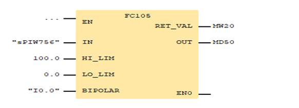
Figure 3.1 — Enter the data for the rolling number
The segment (Fig. 3.1) compares the data coming from the sensor with tabular values for onward transmission. The number of such segments corresponds to the number of rows in table 3.1.
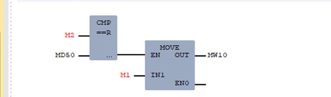
Figure 3.2 – Comparison of real values with tabular
When comparing all 13 segments, one of them should work, and output the necessary value to the last segment corresponding to the table. Further, this value is displayed on the periphery and on the actuators as shown in Fig.3.3
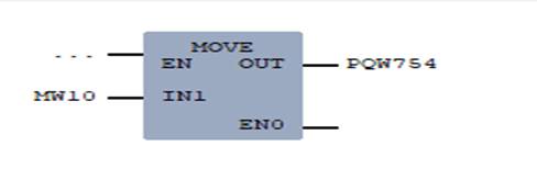
Figure 3.3 – Outputting values to peripheral control devices
Thus, the table values of the specified parameters can be entered into programmable logic controllers, which allows you to automate the function of their choice and improve the working conditions of process operators.
References
- ПЛК Vipa [Электронный ресурс]. Режим доступа: Yaskawa Vipa Controls .
- Федоряк Р., Лейковский К., Светличный А. Система контроля технологии и управления скоростными режимами прокатного стана// Современные технологии автоматизации. — 2001. — № 1.
- Редакционная статья, прокатное производство, 2013 г.
Режим доступа: Международное изданиеMetallurgical and Mining Industry
. - А.А.Восканьянц Автоматизированное управление процессами прокатки: Учеб. пособие/А.А.Восканьянц; Московский гос.техн. ун-т им. Н.Э.Баумана - М.: МГТУ им Н.Э.Баумана, 2010.- 85 с.
- Pазработка математической модели взаимосвязанных электромеханических систем черновой группы прокатного стана. Андрюшин И. Ю., Шубин А. Г., Гостев А. Н./Электротехнические системы и комплексы. Вып. № 3 (24) 2014 г. - С 24–30.
- Бычков В.П. Электропривод и автоматизация металлургического производства. Учеб. пособие для вузов, 1977, 391 с.
- Фединцев В.Е. Электрооборудование цехов ОМД. Ч.2. Электропривод прокатных станов и вспомогательных механизмов цехов ОМД: Учеб. Пособие.-М.:МИСиС, 2005. - 119 с.