
Abstract
Content
- Introduction
- 1. Relevance of the topic
- 2. Goal and tasks of the research
- 3. Effect of thermal pollution on the environment
- 4. Ways of excess heat in the biosphere
- 5. Low potential heat recovery methods
- Conclusion
- References
Introduction
Human habitat is the natural environment, and the basis of being of a modern civilization is fossil natural resources and energy generated from them. Obviously, without energy, humanity has no future. But on the other hand, energy production has a powerful negative impact on the environment, worsening the living conditions of people [1].
Electric energy is produced through the use of potential energy hidden in various natural resources. This occurs mainly in thermal (TPP) and nuclear power plants (NPP), operating on a thermal cycle.
Thermal power plant (TPP) is a complex multicomponent system consisting of a large number of subsystems and units. Thermal power plants have basic and ensuring technological processes, production with a very high level of environmental pollution. Figure 1 shows a diagram of the interaction of a thermal power plant with the environment.
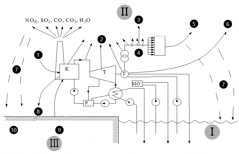
Figure 1 – Diagram of the interaction of thermal power plants with the environment
I – hydrosphere; II – the atmosphere; III – lithosphere
K – boiler; T – turbine, P – regenerative heating of feed water; G – generator; MO – oil cooler
1 – air; 2 – heat, noise; 3 – electromagnetic fields; 4 power lines; 5 – heat; 6 – steam; 7 – precipitation; 8 – sludge; 9 – fossil fuels; 10 – change the landscape
The main environmental problems of coal –fired power plants include: dusting during storage and transportation of coal; entry into the biosphere of fuel combustion products in boilers; steam cooling in turbines; discharges of polluted water into water bodies; storage of sludge in ash dumps, etc.
When burning fuel at TPPs, its entire mass becomes waste, and the products of combustion are several times the mass of fuel due to the inclusion of nitrogen and oxygen.
Atmospheric air pollution to a greater extent occurs during fuel combustion. The main components include: dust particles of different composition, oxides of sulfur and nitrogen, fluoride compounds, metal oxides, gaseous products of incomplete combustion of fuel. In general, air pollution by industrial waste heat and power emissions of harmful substances are: for solid (ash) – up to 35%; sulfur dioxide – up to 50%; nitrogen oxides – up to 35%. Their entry into the air environment causes great damage to all major components of the biosphere, as well as to enterprises, urban facilities, transport and the population of cities.
One of the factors of the interaction of thermal power plants with the aquatic environment is the consumption of water by technical water supply systems, including irretrievable water consumption. The discharge of wastewater into reservoirs has a detrimental effect on water quality and aquatic organisms [2].
The impact of thermal power plants on the lithosphere is as follows: surface discharges and filtration leads to pollution of the adjacent territory; thermal effects lead to a change in the thermal state of the soil; reducing the amount of land suitable for farmland; change of radioactive background of the territory; the accumulation in the soil of heavy metals, which are transferred by groundwater to water bodies.
Thus, the enterprises of thermal power, in general, are one of the main environmental pollutants.
1. Relevance of the topic
In the design and operation of thermal power plants, some units are not given enough attention, their heat losses are considered natural. Such units and systems include turbine generators, TPP transformers, a lubrication system for bearings of the turbine shaft and a turbogenerator, a system for continuous blowdown of boilers. Heat losses of a number of working media, for example, spent steam turbines, are traditionally considered unavoidable due to the low potential of the lost heat, although the presence of low –potential heat losses leads to a significant decrease in the energy efficiency of thermal power plants. Only in the condensers of turbines of large power stations is lost up to 500 MW of thermal power.
Heat losses to the environment lead to negative consequences for the biosphere.
Given the above, one of the most pressing issues of improving the efficiency of TPP operation and the level of environmental safety is the development of technologies that allow to regenerate (return to the cycle) the heat of low potential.
2. Goal and tasks of the research
The purpose of the work is to analyze the environmental problems associated with the excess heat coming into the biosphere from the activities of thermal power plants using the Energy of Donbass EP as the example of the Starobeshevskaya TPP, whose appearance is shown in Figure 2, and to develop measures to reduce thermal pollution of the biosphere.
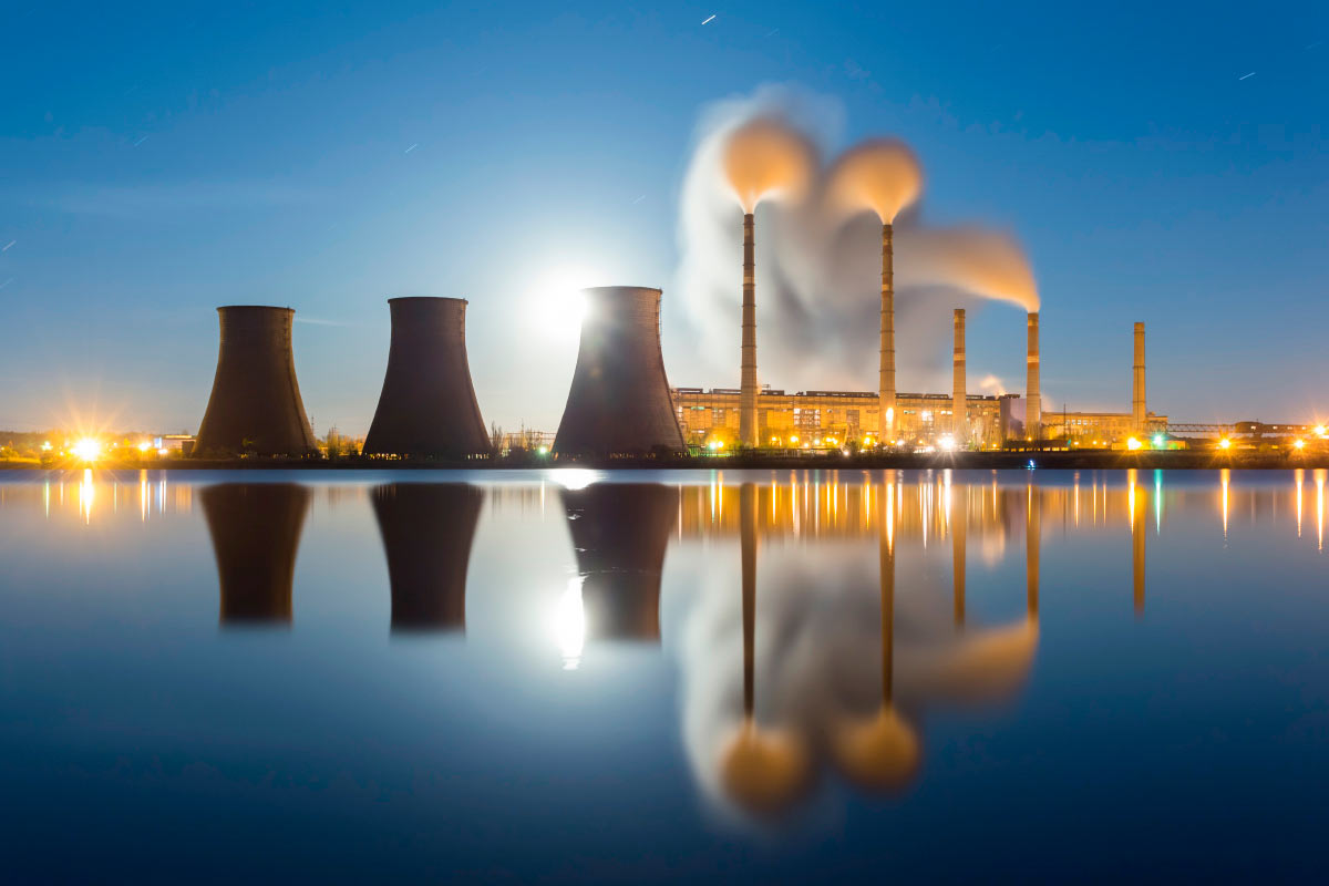
Figure 2 – Appearance of SS Starobeshevskaya TPP
The installed capacity of this TPP is 2300 MW, in operation of 9 power units, the station operates in the maneuvering mode. During 2015 –2018, from 2 to 5 power units are simultaneously in operation. The fuel is coal brand ASH. Technical water supply combined with a reservoir and cooling towers. Electricity is transmitted through high –voltage power lines of 110 and 220 kV. [3].
Objectives of the study:
1 Analyze the effect of thermal pollution on the environment.
2 To study the path of excess heat in the biosphere.
3 Analyze low –potential heat recovery methods that exist in world practice and determine the best heat recovery methods for the Starobeshevskaya TPP.
4 To make an environmental and economic assessment of the developed measures.
The object of study is low –temperature heat fluxes from aggregates and working media of the Starobeshevskaya TPP.
3. Effect of thermal pollution on the environment
Scientists estimate that globally, the heat of anthropogenic origin is still immeasurably small compared with the heat coming from the Sun and from the Earth's bowels and, thus, cannot significantly affect the thermal balance of the Earth [4].
However, powerful sources of anthropogenic emissions of heat, provided they are highly concentrated in small areas, can have a noticeable effect on the thermal regime of these territories, spaces, and waters. The air temperature in winter in large cities is usually several degrees higher than near small settlements. The thermal regime of rivers and lakes also noticeably changes when the heated waste water of thermal power plants is discharged into them. Thus, the influence of powerful anthropogenic heat sources on the biosphere is quite noticeable, although it has a local character [5].
At thermal power plants there are basic and ensuring technological processes, production with a very high level of thermal pollution of the environment.
The greatest negative impact of thermal pollution is on aquatic ecosystems with the following negative effects:
– an increase in water temperature enhances the susceptibility of organisms to toxic substances that are present in polluted water;
– water temperature may exceed critical values for vital stages and cycles of aquatic organisms;
– high temperature contributes to the modification of the usual algae flora to a less desirable form in the form of blue –green algae.
The influence of thermal power plants on the lithosphere consists in pollution of the adjacent territory, thermal effects and changes in the thermal state of soils, changes in the radioactive background of the territory, accumulation of heavy metal compounds in the soil. Heated soil interacts with plants, animals and microbial communities, changing the parameters of the habitat.
Techno genic changes in temperature can worsen the living and working conditions of people. It is also possible to increase the corrosion of materials and damage to heat and gas pipelines, sewage, etc.
4. Ways of excess heat in the biosphere
Essentially, a thermal power plant is a system for converting chemical energy of a fuel into useful electrical and thermal energy. Like any mechanism, a thermal power plant has a certain value of efficiency coefficient of efficiency [6]. Part of the energy of the fuel leaves the station's cycle as a series of side energy flows, which include heat loss from the flue gases, from the purge water, from the exhaust steam of the turbines, in electrical units, due to friction in mechanical devices, etc.
At the same time, there are a number of flows entering the station cycle from the outside; they have a low physical potential close to the potential of the environment. These include make –up water, blast air and fuel.
Currently, among the power plants with installed capacity of more than 1000 MW, condensing –type thermal power plants prevail, including the Starobeshevskaya thermal power station. The efficiency of modern condensation power plants, as a rule, does not exceed 40%, mainly due to the loss of heat carried away by the exhaust gases, together with the combustion products, recycled water required for complete condensation of steam in the turbine, as well as a decrease in steam operating parameters the entrance to the turbine [7].
The reduction of steam parameters is due to the fact that the main equipment of modern thermal power plants, especially those operating on solid fuels, is heavily worn out. The steel from which the boiler equipment is made and the nozzle apparatus of turbine plants is not capable of sustaining the nominal load for a long time, which leads to a decrease in the installed capacity of the power units of TPPs, and this negatively affects the efficiency of the entire power plant [8].
Figure 3 shows a typical scheme of the thermal balance of a condensing thermal power plant.

Figure 3 – Typical heat balance diagram of a condensing thermal power plant
1 – the heat generated by burning fuel; 2 – losses in the boiler room; 3 – pipeline losses; 4 – losses in turbine generators; 5 – loss in the capacitor; 6 – heat converted into electricity
Quantitatively, the most significant are the heat loss from the flow of exhaust steam turbines. The basis of these losses is the latent heat of condensation of water vapor. The exhaust steam is condensed in condensers of various types by taking heat from the refrigerant.
Heat losses during operation of boilers occur due to removal of slag from the furnace, the temperature of which is 1400-1600 оС. When turbogenerators are loaded, heat is generated in its windings and steel. The amount of heat generated depends on the electromagnetic efficiency of the unit.
Taking into account the above, one of the most pressing issues of TPP operation is the development of technologies that allow to regenerate (return to the cycle) the heat of low potential.
5. Low potential heat recovery methods
In the general sense, the term regeneration
means renewal, restoration. With reference to heat fluxes at TPPs, this term implies the return of the energy of a particular flow to the thermal cycle of the station [9].
It is possible to use various technologies for the regeneration of low –temperature heat fluxes from units and working environments of TPPs:
– heats of windings of turbogenerators and transformers;
– the heat of the low –pressure purge water that is not evaporated in the continuous purge separator;
– the heat of the lubricant oil of the turbine shaft and the turbogenerator;
– the apparent and latent heat of the exhaust steam turbines.
Technically, the regeneration of the heat of the windings of a turbogenerator by air or gas consumed by boilers can be implemented in several ways depending on the type of generator and the cooling method used [10]. With hydrogen cooling of the turbogenerator, it is better to perform regeneration by transferring the heat of heated hydrogen to air or natural gas in special gas coolers.
This technology makes it possible to combine the processes of utilization of the heat of the windings of turbogenerators with preliminary preparation of fuel, which makes it possible to increase the economy and environmental safety of the plant by reducing the energy costs of the water cooling system, the air and natural gas preheating system, and also by returning the heat of the turbogenerators to the station's heat cycle.
It is advisable to use the heat of low pressure purge water that is not evaporated in the continuous blowdown separator to preheat the low –temperature reduced natural gas in front of the boiler. The technology allows to achieve the deepest cooling of the purge water. Due to the use of low potential of the reduced natural gas, the temperature of the water at the outlet from the continuous purge cooler does not exceed 3 –5оС, which is 15 –20 оС lower than the ambient temperature during summer time [11].
It is advisable to remove the oil heat from the lubrication system of the bearings of the turbine shaft and the turbogenerator by using air and low –temperature reduced natural gas as a cooling medium for oil coolers. The technology allows almost completely to return the heat of oil of the bearings of the turbine shaft and the turbogenerator to the station cycle, i.e. allows to increase the efficiency of thermal power plants by reducing heat losses to the environment, as well as by reducing the load on the water cooling system.
One of the most effective ways to solve the problem of reducing thermal pollution from the activities of the Starobeshevskaya TPP is to regenerate both the apparent and latent heat of exhaust steam of turbines (the most significant among heat losses – see Figure 3) by using its heat for primary heating of air consumed by TPP boilers, before feeding them into the furnace.
Technically, the air can be heated using exhaust heat in two ways: by replacing a water condenser with an air one, which is connected to the main duct of a boiler fan duct by cooling medium or using a cooling tower with forced air circulation [12].
Technological scheme of the process with the heat recovery of the exhaust steam turbine is presented in Figure 4.
Figure 4 – Diagram of the process with the heat recovery of the exhaust steam turbine
(animation: 3 frames, 10 cycles of repetition, 29,2 kilobytes)
1 – boiler; – burner; 3 – turbine; 4 – capacitor; 5 – air intake; 6 – air outlet; 7 – blower fan
The boiler 1 through the burner 2 serves the fuel and the air produced in the boiler 1 water vapor is sent to the turbine 3. The water vapor in the turbine is condensed in the condenser 4. The main turbine condensate is returned to the boiler 1 through the turbine regeneration system. As the cooling medium of the condenser 4 use atmospheric air, the movement of which is carried out by thrusting the blower fan of the boiler, heated air is fed to the boiler 1. Partially spent steam in the turbine through the extraction pipeline is sent to external consumers.
The technology allows the heat source to be used to preheat the blast air in the low –temperature range, which improves energy efficiency and environmental safety of a thermal power plant by reducing the cost of steam for heating the air before the air heaters, as well as reducing the heat loss of the exhaust steam to the environment.
Also, all the heat generated can be used in a heat pump. A heat pump is a thermodynamic installation in which the low –potential energy of the source is transferred to the consumer already at higher parameters [13].
The principle of operation of the vapor compression heat pump is based on the ability of the working fluid, the refrigerant, to transfer thermal energy. In this case, the main element for increasing the heat energy of the working fluid is the compressor. Supply of low –potential heat is carried out in the heat pump evaporator, due to boiling of the refrigerant under vacuum. At boiling up, a pair of working fluid takes heat from the energy source and enters the compressor, where the process of compression and increase of their thermodynamic parameters occurs. In the condenser, the vapors of the working medium are condensed, giving their thermal energy to the consumer. Despite the cost of additional electrical energy required for the compressor, the heat pump is able to release heat energy 2.5 –5.5 times more, which is its undeniable advantage.
Conclusion
The proposed scheme for regeneration of the heat of the turbine exhaust water vapor involves the use of air and natural gas consumed by the station’s boilers as a condenser refrigerant, which allows reducing the load on the process water circuit and, therefore, avoiding or significantly reducing the listed problems associated with thermal pollution of nearby reservoirs.
It is proved that the application of the proposed technology of low –grade heat recovery allows to increase the energy efficiency of TPP, i.e. allows you to reduce fuel consumption on boilers. It has been established that the use of this technology allows to save up to 29 thousand tons of reference fuel per year (per 100 MW power unit).
The application of the proposed technology will enhance the level of environmental safety of a condensing thermal power plant.
The costs of introducing low potential heat recovery technology at TPPs pay for themselves in less than 2 years per power unit with a TP –100 turbine.
References
1. Росляков, П. В. Методы защиты окружающей среды: Учебник для ВУЗов / П. В. Росляков. – М.: Издательский дом МЭИ, 2007. – 336 с.
2. Беликов, С. Е. , Котлер, В. Р. Котлы тепловых электростанций и защита атмосферы / С. Е. Беликов, В. Р. Котлер. – М.: Энергоатомиздат, 2012. – 327 с.
3. Инвентаризация источников выбросов загрязняющих веществ в атмосферу с 2009 по 2013 год для структурной единицы ПАО Донбассэнерго
Старобешевская ТЭС / ПАО Донбассэнерго
Старобешевская ТЭС – Донецк, 2013. – 180 с.
4. Арсеньев, Г. В. Тепловое оборудование и тепловые сети [Текст] / Г. В. Арсеньев, В. П. Белоусов. – М.: Энергоиздат, 1988. – 284 с.
5. Технология централизованного производства электроэнергии и теплоты: учеб.-метод. пособие к практ. занятиям / С. В. Скубиенко, И. В. Осадчий, Д. А. Шафорост; Юж.-Рос. гос. техн. ун-т. – Новочеркасск: ЮРГТУ, 2010. – 39 с.
6. Быстрицкий, Г. Ф. Энергосиловое оборудование промышленных предприятий / Г. Ф. Быстрицкий. – М.: Издательский центр Академия
, 2003. – 304 с.
7. Основы расчета и проектирования ТЭС и АЭС: Учеб. пособие / С. В. Скубиенко, С. В. Шелепень, В. Н. Балтян – Под общ. ред. С. В. Скубиенко / Юж.-Рос. гос. техн. ун-т. – Новочеркасск: ЮРГТУ, 2004. – 184 с.
8. Трухний, А. Д. , Ломакин, Б. В. Теплофикационные паровые турбины и турбоустановки: Учебное пособие для вузов. – М.: Издательство МЭИ, 2002. – 540 с.
9. Разрешение на специальное водопользование и нормативы предельно допустимых сбросов загрязняющих веществ с возвратными водами структурной единицы ПАО Донбассэнерго
Старобешевская ТЭС / ПАО Донбассэнерго
Старобешевская ТЭС. – Донецк, 2005. – 125 с.
10. Отчет по инвентаризации сбросов загрязняющих веществ от производства ПАО Донбассэнерго
Старобешевская ТЭС / ПАО Донбассэнерго
Старобешевская ТЭС. – Донецк, 2009-2013. – 30 с.
11. Отчет по инвентаризации отходов производства ПАО Донбассэнерго
Старобешевская ТЭС / ПАО Донбассэнерго
Старобешевская ТЭС. – Донецк, 2009-2013. – 155 с.
12. Кравченко, В. С. Пути снижения теплового загрязнения биосферы от предприятий теплоэлектроэнергетики / В. С. Кравченко// сборник докладов ХII Международной конференции аспирантов и студентов / ДОННТУ, ДонНУ. – Донецк: ГОУ ВПО ДОННТУ
, 2018. – С. 178-181
13. Трухний, А. Д. , Ломакин, Б. В. теплофикационные паровые турбины и турбоустановки: Учебное пособие для вузов. – М.: Издательство МЭИ, 2002. – 540 с.