
Abstract
When writing this essay master's work is not yet completed. Final Completion: June 2019. The full text of the work and materials on the topic can be obtained from the author or his manager after the specified date.
Содержание
- Introduction
- 1. Theme urgency
- 2. Goal and tasks of the research
- 3. Review of research and development
- 4. Analysis of pumping apparatus
- 5. Jet-air-lift installation
- References
Introduction
For pumping fluid from wells and water tanks, not only hydrodynamic and volumetric pumps are used, as well as hydro-pneumatic apparatuses - displacement pumps, airlifts, and jet devices. Under the mine conditions, hydrotransport facilities are represented by special drainage and hydrotreating facilities, such as airlifts of various designs, hydraulic elevators, slurry pumps, etc. The use of these tools in mining operations is one of the promising methods for their integrated mechanization.
1. Theme urgency
As indicated above, there are currently a lot of work related to increasing the productivity of pumping units, searching for units that, with relatively small dimensions, will give good performance. In the mines, where maintenance work is difficult, they use airlifts, but they are not very relevant in our time. The master's work will consider a jet-airlift installation, which combines the advantages of airlift and jet apparatus. According to some reports, the installation will be able to replace the airlift as a water transporter, the ash-and-slag cleaning organ.
2. Goal and tasks of the research
The aim of the work is to consider the jet-air-lift installation as such. Building a mathematical model of the installation. Get the results of the parameters for optimal performance.
Main tasks of the research:
- Consideration of the jet apparatus, consideration of airlift with a jet apparatus;
- Construction of a mathematical model of a jet-airlift installation;
- Analysis of the data. Verification of the data using software.
- Justify the economic efficiency of operation of this installation.
Research object: jet-air-lift installation..
Research subject: construction of a mathematical model of a jet-airlift installation.
3. Review of research and development
The monograph [1] summarizes the theoretical foundations, experience in the development and use of submersible pneumatic displacement pumps for pumping fluid during mine workings and flushing wells under conditions of absorption of the cleaning agent. The results of the author’s research on the development and improvement of the reliability of the theory of calculating the operating cycle and supplying pneumatic pumps used for inside the well are presented. The book is intended for professionals practicing all in the field of research, development and implementation of pumping installations in the mining industry and drilling, employees of research organizations of this profile, and can also be useful in mountain universities and faculties.
In the book [2] the basics of the theory, calculation and the order of operation of the airlift are given, which are used to lift the solid from the underground workings of mine drainage, cleaning the underground tanks to remove ash and slag at heat stations. The basics of automation are given. The outlined material is prepared for students of mining and metallurgical specialties and can be used by engineers in the design and operation of aerial installation.
The book [3] outlines the main issues of the theory and practice of periodic gas lift, developed by domestic and foreign researchers. The provisions of the theory of periodic gas lift are analyzed, and on the basis of extensive bench experiments, the essence of the processes occurring during the ejection of a liquid column is highlighted in a new way, besides new patterns are established between various parameters and indicators of the emission process. A classification system is proposed that allows you to accurately and reliably select the type of periodic installation that is most suitable for these conditions, as well as a new calculation of the parameters of the installation and the experimental method for establishing the operating mode of the well.
In the book [4] the theory of the method of calculating jet apparatus is described. The basic design equations are illustrated with examples. Nomograms for determining the achievable parameters and the optimal ratio of the cross sections of the apparatus with a cylindrical mixing chamber are given. The proposed classification of jet apparatus. The results of experimental studies that substantiate the correctness of the calculated dependences and recommended experimental coefficients for inkjet apparatus with elastic and non-elastic media are given.
4. Analysis of pumping apparatus
Pneumatic displacement pumps are devices that work with full or partial use of the potential energy of compressed air Pneumatic displacement pumps are recommended to be classified on the basis of the energy indicator - efficiency. According to this indicator, they are differentiated into pumps:
- Working with full or partial use of the potential energy of compressed air (first-class chamber-type pumps);
- Working without using the potential energy of compressed air (pumps of the second class of the chamber of the elite type with a fluid supply stationary and unsteady flow).
This principle of classification determines the quality characteristics of pumps and connects them to a certain system based on the main energy indicator - efficiency.
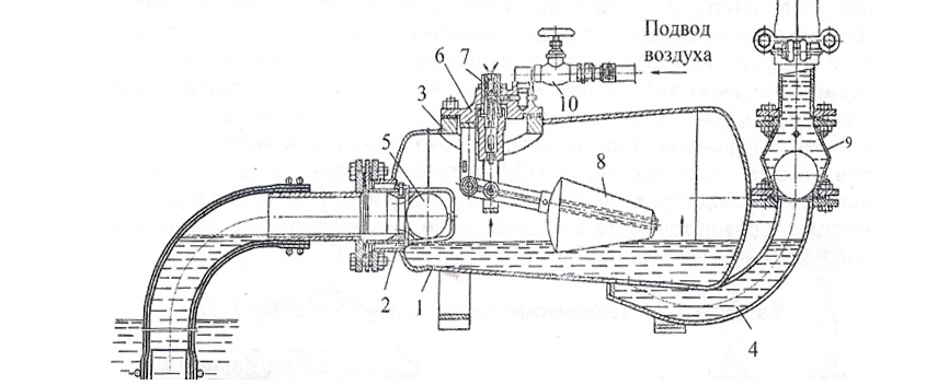
Pneumatic pump NZU: 1-body; 2-flanged suction connection; 3-window for control cover; 4- discharge pipe; 5 valve suction; 6-control cover; 7-conical surface of the ejector; 8-float; 9-way valve; 10-valve.
When the air valve is opened, the compressed air flows through the annular ejector into the atmosphere, creating a vacuum in the pump casing. At the same time, the valve ball on the suction pipe rolls away from the seat to the extreme position, opening the suction port. Under the influence of the atmosphere, the liquid flows through the suction hose to the pump. As the pump is filled with liquid, the float moves up to its extreme position.
In this case, the piston blocks the exit of air into the atmosphere, and the compressed air through the slotted grooves in the ejector housing enters inside and creates pressure on the surface of the water in the pump. The suction valve ball closes the openings of the suction line, and the fluid from the pump casing is pushed into the discharge line. As the liquid is displaced into the injection pipe, the float is lowered. In the lowest position, it retracts the piston to the lower position, the compressed air enters the ejector again, and the cycle repeats.
The advantages of this device are that it does not require lubrication, and is also self-regulating.
The disadvantages include:
- Low Efficiency;
- Low camera volume (which is the reason for low productivity);
- Limiting lift height;
- Periodic use.
The goal of increasing productivity is to combine two pneumatic pumps in one unit. In this case, it is necessary to have a common management staff, whose role is to alternately feed the unit into one or another chamber of the installation. Two-chamber installations can be used for pumping and pumping fluids from the teeth and local water collections.
With the use of compressed air in the discharge pipe, such installations can also be used for pumping fluid from chambers when conducting vertical shafts and for pumping water from horizon to horizon.
Airlift – pneumatic pump, which carries out the pumping of liquid through the use of the energy of the injected air or gas (gas lift).
The mixture (air and fluid) is moved due to the difference in the power of the air flow introduced into the airlift and the mixture leaving it. The required power difference is generated by the compressor.
Airlift workflow
(animation: 21 frames, 5 cycles of repetition, 108 kilobytes)
(1 - air supply pipe; 2 - mixer; 3 - suction device; 4 - lifting pipe; 5 - air separator; Qp - air consumption; Qe - airlift delivery; h - immersion of a mixer; H - lift height of the slurry.)
The air line is connected to the compressor, which creates pressure in the mixer sufficient to force the liquid out of the air line and ensure its transportation through the airlift pipe to the air separator. In the air separator, air and liquid are separated. Then the liquid flows through the drain pipe.
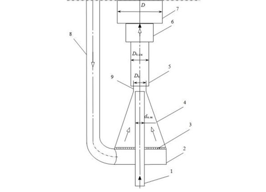
The supply of airlift depends on the depth of the dive, as well as the relative dive:
<
The main advantages of airlifts include:
- Simplicity of design;
- No moving parts.
The disadvantages include:
- Low efficiency (coefficient of performance);
- Flow problems at shallow depths;
- Lack of mobility.
For those cases when α <0.15, special types of airlifts are used – air-lift with elements of the jet apparatus .
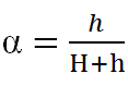
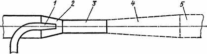
Mixer diagram with elements of the jet apparatus: 1- supply pipe; 2- cylindrical collector; 3-lattice base; 4- conical nozzles; 5- cylindrical mixing chamber; 6- transition section; 7- lifting pipeline; 8-air duct; 9 - the initial section.
Airlift installation, equipped with a mixer with elements of a jet apparatus, contains a lifting pipe 7, an air line 8 connected to a cylindrical collector 2 on which a conical nozzle 4 is installed with a base made in the form of a grid 3, a supply pipe 1, a cylindrical mixing chamber 5 The mixing chamber contains the initial section 9 and the transition section 6. The output section of the supply pipe 1 is located in the same plane as the transition point of the conical nozzle 4 into the initial section 9 of the mixing chamber and forms with it an obverse crack for the admission of compressed air into the mixing chamber. The design of the mixer contributes to the streamlining of the structure and the creation of a rational field of velocity of compressed air flow before entering the ring chain; allows you to use the kinetic energy of compressed air in the annular gap.
The disadvantage of such an airlift is low efficiency and the required depth of the airlift mixer (h).
In cases of impossibility to ensure the immersion depth, apply jet devices .
Jet apparat
Inkjet apparatus, a device for injecting or sucking liquid (gaseous) substances, based on the exchange of mechanical energy of two flows of substances in the process of mixing them. A stream with a higher pressure is called a working (or working medium flow).
Their use is advisable, for example, if there is a working fluid under high pressure (in particular, in heating networks), and also if the suction fluid is not allowed to pass through the working body of an acting supercharger (for example, when pumping slurry or sucking explosive gases ).
During flow, a jet through a nozzle in it dramatically increases the speed and dynamic pressure, as a result of which the static pressure decreases accordingly. At the outflow of the fluid, where the speed is maximum, a significant vacuum is created, so that the suction fluid rushes into the annular gap between the nozzle and the receiving chamber, which is mixed with the working fluid and injected into the network [ 6 ].
Depending on the type of working fluid (gas, steam or water), jet blowers are called ejectors, injectors and elevators. Any such apparatus can move gas or water, i.e. it can act as a pump, fan, compressor. This is done much less economically, although incomparably easier.
The advantage of jet devices is that the depth of immersion is not obligatory for them, but of the drawbacks is low efficiency.
5. Jet-air-lift installation
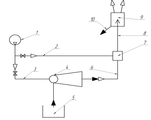
Scheme of the jet-air-lift installation: 1-compressor; 2- discharge air duct (to the mixer); 3- discharge air duct (to CA); 4-jet apparatus (CA); 5 - water collector; 6-injection network; 7- mixer; 8- lifting pipe; 9- air separator; 10- drain pipe.
In the presented installation, air is supplied from compressor 1 by means of air ducts 3, 2 to the jet device 4 and mixer 7, then the liquid is pumped out from the water collector 5 due to the pressure difference. Next, the air-water mixture enters the injection pipe 6, creating an artificial immersion. Then, through the mixer, through the lifting pipe 8, the mixture enters the air separator 9, from which water is discharged to the destination through the pipeline 10.
The following dependencies [4] form the basis of the mathematical model of the workflow of a jet-air-lift installation:
- Relative immersion of a jet - air lift installation
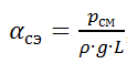
where pcm – overpressure in the mixer; L– the length of the lifting pipe airlift;
- Relative pressure (gas dynamic tables [4])
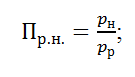
where pn–the pressure of the injected stream;pp–workflow pressure;
- Optimal section ratio
 :
:
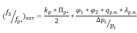
where f3 – the output section of the mixing chamber; fp* – nozzle throat area;δpc=p c -p n – differential injected and output pressure;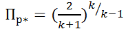 is the value of the relative pressure (Pp* ≈ 0.528);φ 1, φ2 – flow rates; q rn. is the reduced speed of the workflow; λ rn. - gas-dynamic function;
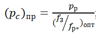
 - Limit value of network pressure (pressure at the outlet of the apparatus)
- Injection rate
u = ut - ur
as the gas-water jet apparatus sucks the liquid not mixed with gas, then u r = 0, therefore: u = u t ; - Injection rate for solid
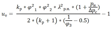
where φ 3 – coefficient of flow velocity, kp – adiabatic index.
The solution of the mathematical model of the workflow of the jet-air-lift installation will make it possible to determine the rational modes of its operation.
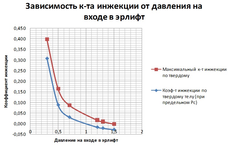
From the graph above, it can be seen that the injection coefficient depends on the pressure at the inlet to the airlift (pressure at the outlet of the jet apparatus). To increase the injection ratio of the machine in the design mode, select the ratio of the cross section from the condition of equality of the design and maximum compression pressure pc pr = p s = 0.3 MPa.
References
- Филимоненко Н.Т. Пневматические насосы вытеснения: монография/ Н.Т. Филимоненко. - Донецк: из-во «Ноулидж» (Донецкое отделение) 2012.- 294 стр.
- Эрлифтные установки: Учебное пособие/ Гейер В. Г., Козыряцкий Л. Н., Пащенко В. С., Антонов Я. К. - Донецк : ДПИ, 1982. 64 стр.
- Белов. И.Г. Теория и практика периодического газлифта. М., «Недра», 1975, 144стр.
- Соколов Е. Я., Зингер Н. М., Струйные аппараты, Изд. 2, М., «Энергия»,1970. 288 стр.
- Божко Р.И., Обоснование параметров рабочего процесса эрлифтной установки для гидроочистки шахтных водоотливных емкостей [электронный ресурс]: http://masters.donntu.ru/2014/fimm/bozhko/diss/index.htm.
- Строительный информационный портал, [электронный ресурс]: http://www.stroitelstvo-new.ru/nagnetateli/tipy-strujnyh-apparatov.shtml.