
Abstract
- Introduction
- 1. Actualite of the topic
- 2. Goal and tasks of the research
- 3. Device and principle of operation of an air-lift unit with a jet apparatus
- Review of research and development
- Conclusions
- References
Introduction
One of the directions of technical progress is the development of hydraulic transport, in which fluid flows carry loose or solid particles.
In mine conditions, hydrotransport means are represented by special means of water drainage and hydrotreating, such as air lifts of various designs, slurry pumps, etc. The use of these means in mining operations – one of the promising ways of their complex mechanization.
Airlift (air lift) is a hydraulic apparatus for lifting a dropping liquid, or a dropping liquid and a solid material by using air (gas, steam) compressed in a supercharger and mixed with this dropping liquid.
Airlifts are also used for:
1) supply of active circulating sludge and raising the waste liquid to a small height at the sewage treatment plants;
2) supply of chemicals at water treatment plants;
3) lifting water from wells of different depths;
4) pumping oil from underground sources;
5) mining of minerals from the bottom of rivers, lakes, seas and oceans;
6) ash and slag removal at TPPs operating on solid fuel.
Experience has shown that, along with some drawbacks (main – low efficiency), airlifts have a number of advantages: simplicity of the device, no moving parts, the possibility of suspension in the transported fluid.
Inkjet device for injecting or sucking liquid (gaseous) substances, based on the exchange of mechanical energy of two streams of substances in the process of mixing them.
The efficiency of the jet apparatus does not exceed 30%, however, the possibility of increasing the pressure of the suction flow with moving parts, simplicity of design, reliability of operation provided the use of jet apparatus in many branches of technology. With significant costs of a compressible medium and at high pressures, more economical, but also more complex mechanical blowers (pumps, compressors, fans, etc.) are used.
1.Actualite of the topic
Overpressure in mine pneumatic networks – 0.5 ... 0.6 MPa, which, as a rule, is greater than the required pressure for the operation of the airlift, used for overpressure in the pneumatic network in mine conditions. An air–lift unit with a jet apparatus in an air duct allows to reduce the flow of compressed air from the pneumatic network and increase the energy dependence of the unit operation.
2. Goal and tasks of the research
The aim of the master's thesis is to increase the energy efficiency of an air–lift installation by utilizing the excess energy of compressed air coming from the mine pneumatic network in a jet device.
Main tasks of the research:
- modeling and analysis of the features of the operation of an air–lift unit with a jet apparatus;
- calculation and modeling of the gas–jet compressor workflow;
- plotting the dependences of the jet injection ratio on the pressures of the working and injected flows;
- consideration of ways to improve the efficiency of the gas–jet compressor when:
• pulsating flow of workflow;
• improving the design of the jet apparatus (working nozzle, mixing chamber, etc.).
3. Device and principle of operation of an air–lift unit with a jet apparatus
Figure 1 shows a diagram of an air–lift installation with a jet apparatus in an air duct, which shows the main structural elements, as well as geometric parameters.
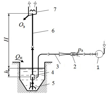
Figure 1 – Air lift with jet apparatus :
1 – compressor; 2 – ejector; 3 – ; 4
air duct –
mixer; 5 – suction device; 6 –
lifting pipe; 7 – air separator; h – geometric depth; H – lift height
; Qп –
fluid influx; Qэ – air lift.
The use of an inject apparatus as part of an air–lift system makes it possible to achieve a reduction in compressed air consumption due to the utilization of excess pressure in the network above the pressure in the mixer
Compressed air from compressor 1 enters the jet apparatus 2, in which it mixes with atmospheric air and compresses the mixed gas to a pressure determined by the geometric immersion of the mixer. When air is supplied to the air duct 3, the process of displacing the liquid through the mixer 4 into the riser pipe 6, as well as through the supply pipe of the suction device 5, begins.
After the liquid is completely displaced from the air supply pipe, air enters the mixer, where the process of mixing air (gas) with the liquid occurs and the air mixture begins to fill the lifting pipe.
The subsequent increase in air flow leads to the expiration of the water–air mixture from the riser pipe into the air separator 7, where air and liquid are separated. The pressure in the mixer at the same time will be lower than the pressure of the surrounding liquid column, because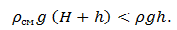
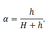
The main characteristic dimensionless parameter for airlift installations is relative immersion.[1]
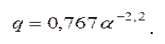
The specific air flow rate (in the optimal mode) for short airlifts is [1]
The gas-jet compressor is a pneumatic device, which also contains no moving parts(figure 2).
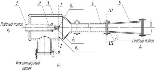
Figure 2 – Gas jet compressor:
1 – workflow pipeline; 2 – working nozzle; 3 – receiving chamber; 4 – mixing chamber; 5 – diffuser; 6 –
injection flow; pн –
injection pressure; pр –
workflow pressure; pс –
pressure of compressed flow.
The flows of the working and injected media enter the mixing chamber 3, where the velocity is equalized, which is usually accompanied by an increase in pressure. From the mixing chamber, the flow enters the diffuser 5, where there is a further increase in pressure. The pressure of the mixed flow at the outlet of the diffuser is higher than the pressure of the injected flow entering the receiving chamber.
The principle of operation of the gas–jet compressor is shown on the figure 3 [11].
Figure 3 – The principle of operation of the gas–jet compressor
(Animation: 5 frames, 5 cycles of repetition, 30 kilobytes)
Injection ratio of gas jet apparatus [2]
 ,
,
where Gн – mass flow rate of injected flow;
Gр – workflow.
The equation for calculating the rate of injection of a gas– jet compressor [2]
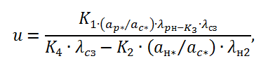 ,
,
where:K1, K2, K3 – speed coefficients of the working, injected flow;
aр*, aн*, aс* – critical speeds of worker, injected and compressed streams;

Critical section of the expanding nozzle [2]
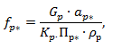 ,
,
where:pp – workflow pressure;
Gр – mass flow rate;
Kр – adiabatic factor.
To build the dependence of the injection coefficient on the pressure of the working and injected pressures [pc/pн=f(u)] you need to know two basic geometrical parameters – the ratio of sections fp1/fp* and f3/fp*, also the external parameters of the two threads: worker and injected (pp, pн, Тн, Тр) or working and compressed,
where: pp, pн, Тн – working, injected and compressed gas pressure;
Тн, Тр – working and injected flow temperature.
Nozzle exit area fp1 determined from dependencies [2].
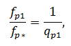 ,
,
where:qp1 – reduced mass flow rate;
fр* – workflow critical section.
The area of the output section of the mixing chamber f3 [2].
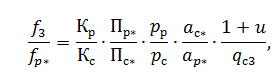 ,
,
where:Kc – compressed flow adiabatic index;
Пс* – relative pressure of compressed flow in the critical section;
qс3 – reduced compressed mass flow rate.
Comparison of experimental characteristics pc/pн=f(u) with a calculated dependence for an achievable injection rate at f3/fp* = 7,6; 14,2; 21,6 mm; pp/pн=6, (figure 4) the adequacy of the analytical method of calculating the parameters of the jet apparatus [2].
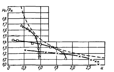
Figure 4 – Comparison of analytical and experimentally obtained characteristics pc/pн=f(u) jet apparatus with a calculated dependence for the attainable injection rate:
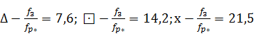
Solid lines (figure 4) applied experimental characteristics pc/pн=f(u) gas jet compressor of three different geometrical parameters, dashed line – calculated dependence pc/pн=f(u).
When reducing the degree of compression, the injection ratio of the apparatus increases to a certain limit Uпp. When operating in the limiting mode, the injection ratio of the gas–jet compressor remains constant. In this mode, the device develops the highest possible performance at a given pressure of the workflow. pp.
Ways to increase the efficiency of jet apparatus
The efficiency of the jet apparatus can be increased by:
• improving the geometric shapes of the flowthrough part of the jet compressor (working nozzle, mixing chamber, etc.;
• creating injectors with intermittent flow of the active flow, which is one of the most effective methods.
• use of multi–stage structures to obtain high degrees of compression;
• Applying the principle of continuous regulation in devices by inserting a needle
into the nozzle by installing an elastic hollow sleeve at the nozzle exit, which is crimped when the nozzle is rotating.
Review of research and development
The source [1] , [2] , [7] , [5] outlines the basics of the theory and calculation of airlifts, the results of numerous experimental studies of airlifts for various purposes, constructive and circuit design of installations operating on homogeneous fluids and hydraulic mixtures, describes the parameters and characteristics of existing airlift installations and issues of the future use of airlifts. In [3] , [8] , [10] the expenditure and energy–mechanical characteristics of airlifts based on the theory of dimensions are considered, similarity criteria for their modeling are given, the classification of airlift and airlift– earth equipment and systems, their purpose, principles of operation, design features, calculation and design principles are given. The source [4] , [6], [9] describes new schemes for gas ejectors with improved characteristics, their creation and use. The source [17] presents the results of theoretical and experimental studies of two-phase jet devices of various types, examines the physical features of the flow of two-phase media in the flow part of the device.
Conclusions
Air-lift installation with a jet device in the duct is used for disposal of overpressure in the pneumatic network in mine conditions. Among the methods discussed above for increasing the efficiency of a gas–jet compressor, one of the most effective is the pulsating flow of the working stream.
When writing this essay master's work is not yet completed. Final Completion: July 2019. Full text of the work and materials on the topic can be obtained from the author or his manager after the specified date.
References
- Энциклопедия эрлифтов / Ф.А. Папаяни, Л.Н. Козыряцкий, В.С. Пащенко, А.П. Кононенко. – М.: Информсвязьиздат, 1995. – 592 с.
- Струйные аппараты / Е.Я. Соколов, Н.М. Зингер. – 3–е изд., перераб. – М:. Энергоатомиздат, 1989. – 352 с.
- Гідромеханізація: навчальний посібник. М.Г. Бойко, В.М. Моргунов, Л.М. Козиряцький, О.В. Федоров. – Донецьк: ДНВЗДонНТУ, 2011. – 554 с.
- Новые газовые эжекторы и эжекционные процессы / Ю. К. Аркадов. – М.: Изд – во Физико – математической литературы, 2001. – 336 с.
- Струйные аппараты / В.Г. Цегельский. – Москва: Издательство МГТУ им. Н.Э. Баумана, 2017. – 573 с.
- Жлобич, А. В. Некоторые особенности работы эжектора на пульсирующем потоке газа / А. В. Жлобич // Труды ТЭМИИТ / ТЭМИИТ – 1960. – вып. 29.– С. 214–225.
- Кононенко А.П. Теория и рабочий процесс эрлифтов. Дис. докт. техн. наук. – Харьков: НТУ “ХПИ”, 2007. – 565 с.
- Гидроподъем полезных ископаемых / Я.К. Антонов, Л.Н. Козыряцкий, В.А. Малашкмна и др. – М.: Недра, 1995. – 173 с.
- Нестационарные задачи газодинамики / Р.Н. Зауэр – М.: МИР, 1969. – 231 с.
- Бессонов Е.А. Технология и механизация гидромеханизированных работ: Справочное пособие для инженеров и техников. – М.: Центр, 1999.
- Работа ежектора [электронный ресурс] [https://www.transvac.co.uk/...].
- Божко Р.И. Обоснование параметров рабочего процесса эрлифтной установки для гидроочистки шахтных водоотливных емкостей: Портал магистров [электронный ресурс] http://masters.donntu.ru/...].
- Струйные насосы [электронный ресурс] [https://studfiles.net/...].
- Исследование характеристик газо–газовых бездиффузорных струйных аппаратов [электронный ресурс] [ http://www.dslib.net/...].
- Двухфазные струйные аппараты. – М.: Изд – во МГТУ им. Н.Э. Баумана, 2003. – 408 с.: ил.
- Эрлифты: устройство, особенности работы [электронный ресурс] [https://topas-site.ru/...].
- Эжектор [электронный ресурс] [http://ru.teplowiki.org/...].
- Гарбуз А.А., Тонконогий Ю.Л. Исследование характеристик низконапорного газового эжектора // Изв. вузов. Энергетика. 1978. №2. с. 75 – 80.
- Коган П.А., Шамис И.А., Якушин А.Н. Определение оптимальных геометрических характеристик газоструйных аппаратов //
- Теплоэнергетика. 1967. №9. С. 69 – 73.
- Коган П.А., Якушин А. Н. К расчету придельных режимов газоструйных аппаратов // Теплоэнергетика. 1969. №11. С. 86 – 87.
- Соколов Е.Я. Расчет и построение характеристик пароструйных компрессоров и водоструйных насосов с цилиндрической камерой смешения // Изв. ВТИ. 1948. №9. С. 19 – 25.
- Соколов Е.Я. Экспериментальные исследования пароструйных компрессоров // Изв. ВТИ. 1948. №11. С. 14 – 21.