
Abstract
Content
- Introduction
- 1. IHP schematic diagram
- 2. Composition and principle of operation of modular IHP
- 3. Review and analysis of possible solutions
- 4. Justification of the accepted direction of solving the problem
- Findings
- List of sources
Introduction
Energy saving and energy enhancement issues – and resource efficiency — one of the key in the development and modernization of various sectors of the regional economy. That is why recently this subject has received close attention at various levels.
In the structure of energy consumption in Donbass, the main consumer — This housing and communal services. Therefore, measures aimed at improving the energy efficiency of residential and administrative buildings are important.
Heating systems have the greatest potential for energy conservation. The latter are required to maintain the parameters of the internal climate of the building at a comfortable human level, reducing energy consumption and increasing the energy efficiency of engineering systems.
Heat consumption regimes, and, consequently, the production of heat energy, depend, as is well known, on a large number of factors: weather conditions, the thermal performance of heated buildings and structures, the characteristics of the heat network and energy sources, etc. When choosing these modes, it is impossible not to take into account the functional interrelationships of the heating system with other engineering systems: electricity, gas, water supply.
The introduction of automated process control systems in the practice of district heating and district heating allows to dramatically increase the technical level of operation of these systems and provide significant fuel savings. In addition to fuel economy, the automation of the systems under consideration allows improving the quality of heating of buildings, increasing the level of thermal comfort and efficiency of industrial and agricultural production in heated buildings, as well as the reliability of heat supply while reducing the number of service personnel.
In my work, as a solution, I propose to use an Individual Heat Point. This is the most important component of building heat supply systems. The regulation of heating systems and hot water supply (DHW), as well as the efficiency of the use of thermal energy, largely depends on its characteristics. Therefore, thermal points receive great attention during the thermal modernization of buildings.
1. IHP schematic diagram
In modern ITP, energy saving is achieved, in particular, by regulating the temperature of the coolant, taking into account the amendment to the change in outdoor temperature. For these purposes, a set of equipment is used at each heat point (Fig. 1) to provide the necessary circulation in the heating system (circulation pumps) and temperature control of the heat carrier (control valves with electric actuators, controllers with temperature sensors).
Figure 1 – Schematic diagram of an individual heat supply station using a controller, a control valve and a circulation pump
Most heat points incorporate a heat exchanger for connection to an internal hot water supply system (DHW) with a circulation pump. The set of equipment depends on the specific tasks and source data. That is why, because of the various possible design options, as well as its compactness and transportability, modern ITPs are called modular.
2. Composition and principle of operation of modular IHP
To implement my thesis, I decided to use a modular ITP. Modular ITPs can be connected to external heating networks via a dependent and independent scheme.
In an IHP with dependent connection of the heating system to external heating networks, the circulation of the coolant in the heating circuit is supported by a circulation pump. The pump is controlled in automatic mode from the controller or from the corresponding control unit. Automatic maintenance of the required temperature schedule in the heating circuit is also carried out by an electronic controller. The controller acts on a control valve located on the supply pipe on the side of the external heat network (“hot water”). A mixing jumper with a check valve is installed between the supply and return pipelines, due to which the mixing flow into the supply pipeline from the return line of the heat carrier is carried out, with lower temperature parameters (Fig. 2).
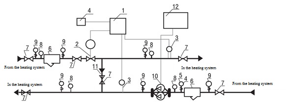
Figure 2 – Schematic diagram of a modular heat point connected by dependent circuits
On Fig. 2 marked: 1 – controller; 2 – two-way control valve with electric drive; 3 – coolant temperature sensors; 4 – outdoor temperature sensor; 5 – pressure switch to protect pumps from running dry; 6 – filters; 7 – gate valves; 8 – thermometers; 9 – pressure gauges; 10 – circulation pumps of the heating system; 11 – check valve; 12 – control unit circulation pumps.
In this scheme, the operation of the heating system depends on the pressure in the central heating network. Therefore, in many cases, it will be necessary to install pressure differential regulators, and, if necessary, pressure regulators "after themselves" or "before themselves" on the supply or return pipelines.
In an independent ITP system, a heat exchanger is used to connect to an external heat source (Fig. 3). The circulation of the coolant in the heating system is carried out by a circulation pump. The pump is controlled automatically by a controller or an appropriate control unit. Automatic maintenance of the required temperature schedule in the heated circuit is also carried out by an electronic controller. The controller acts on an adjustable valve located on the supply pipe on the side of the external heat network (“hot water”).
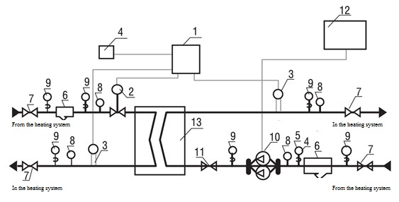
Figure 3 – Schematic diagram of an individual heat point station using a controller, a control valve and a circulation pump
On Fig. 3 marked: 1 – controller; 2 – two-way control valve with electric drive; 3 – coolant temperature sensors; 4 – outdoor temperature sensor; 5 – pressure switch to protect pumps from running dry; 6 – filters; 7 – gate valves; 8 – thermometers; 9 – pressure gauges; 10 – circulation pumps of the heating system; 11 – check valve; 12 – control unit for circulation pumps; 13 – heating system heat exchanger.
The advantage of this scheme is that the heating circuit is independent of the hydraulic modes of the centralized heat network. Also, the heating system does not suffer from inconsistencies in the quality of the incoming coolant coming from the central heating network (availability of corrosion products, dirt, sand, etc.), as well as pressure drops in it. The disadvantage of this scheme is the cost of capital investments when applying an independent scheme. Cost is more than – due to the need to install and subsequent maintenance of the heat exchanger by a qualified technician.
3. Review and analysis of possible solutions
I offer 2 options for ACS for modular ITP — with feedback and combined communication
The system with feedback allows you to measure the temperature of the water at the ITP outlet using a temperature sensor and correct it if necessary, taking into account the disturbing effect of the return water.
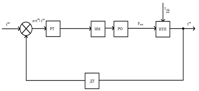
Figure 4 – Block diagram of ACS ITP with feedback
On Fig. 4 marked:: tзад – Desired temperature, tтек – current temperature, e – mismatch signal, tобр.вод – return water temperature, Fвод – the flow of hot water from the heat network going to the heat exchange, РТ – temperature controller, ИМ – actuator, РО – Regulator, ИТП – individual heat point, ДТ – temperature sensor.
The disadvantage of this system is that the disturbing influences are processed by the system after the regulation has taken place, as a result of which the current temperature will differ from the set one.
In order to increase the efficiency of regulation, you can use a closed system with a combined link (Fig. 5).
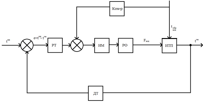
Figure 5 – Block diagram of ACS ITP with a combined link
On Fig. 5 marked: tзад – Desired temperature, tтек – current temperature, e – mismatch signal, tобр.вод – return water temperature, Fвод – the flow of hot water from the heat network going to the heat exchange, РТ – temperature controller, ИМ – actuator, РО – Regulator, ИТП – individual heat point, ДТ – temperature sensor, Ком-р – compensator
With this concept, the disturbing effect is taken into account and compensated before the signal goes to the actuator, therefore, as a result of the regulation at the output of the individual substation, the current temperature will have the necessary parameters.
4.Justification of the accepted direction of solving the problem
After analyzing and evaluating the advantages and disadvantages of the developed alternative versions of the concepts of automatic control systems, it was decided to apply the concept of a closed system with a combined link, as it should show the best result (Fig. 5). The introduction of such a concept will provide an accurate and high-quality result at the output of an ACS with a relatively high performance indicator..
You should not also forget that in the process of writing the master's work this scheme will change and it is not final.
From technical literature it is known that if we consider an ITP as a black box with an input in the form of water flow and an output in the form of temperature, then the behavior of the ITP can be described by the following transfer function:
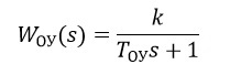
k — gain equal to the ratio of temperature to water flow required to maintain this temperature;
Toу — time constant of the control object.
The actuator and the working body can also be described by the transfer functions of the aperiodic link of the first order.
Simulation of transient processes in ACS ITP was carried out in the simulink package of the Matlab software package.
In the process of tuning and analyzing the regulator, it became clear that only the integral component produces the main influence, therefore, for ease of implementation, we accept an I-controller.
After analyzing the results, I was convinced that the required temperature was reached. The process behaves stably on all graphs, the oscillatory process is not observed. Since I was convinced that the I-controller is suitable for us, a disturbing influence was applied to check the operation of the ACS in the presence of disturbances. The temperature of the water from the return pipeline is supplied as a disturbance.
After analyzing the data, I was convinced that the tasks were completed. The system does not work at the limit of its capabilities after a disturbing action is applied to it, the temperature returns to the desired value in a reasonable time.
Findings
The individual heat point is considered as an object of management.
Analysis of the parameters affecting the operating mode of an individual heat supply station, allowed to draw up a block diagram of the control object. The control action was taken water flow from the heating system. The output parameter is the temperature at the ITP output.
The existing automation schemes with similar objects were analyzed, their advantages and disadvantages were identified in the context of the problem to be solved, and the study concluded that for the given conditions a control concept would be chosen using combined communication.
List of sources
- Сайт Оборудования для автоматизации компании «ОВЕН» [Электронный ресурс]. / – Режим доступа: http://www.owen.ru/.
- Тимошенко Г.М. Научные основы проектирования и эксплуатации насосных установок в переходных режимах. / Тимошенко Г.М. – Киев; Донецк: Вища шк. Головное изд-во, 1986.–127 с.
- Башарин А.В. Управление электроприводами: Учебное пособие для вузов. / Башарин А.В., Новиков В.А., Соколовский Г.Г. – Л.: Энергоиздат. Ленинградское отделение, 1982.–392 с.
- Денисенко В. В. ПИД–регуляторы вопросы реализации часть 2 / Денисенко В. В. – М.: СТА 2008. № 1. с 86-99
- Густав Олсон, Джангуидо Пиани Цифровые системы автоматизации и управления. Санкт–Петербург, 2001.- 557 с.
- Зайцев Г.Ф. Теория автоматического управления и регулирования. / Зайцев Г.Ф. – Киев: Вища школа, 1988 – 431 с.
- Лукас В. А. Теория автоматического управления. / Лукас В. А. – М.: Недра, 1990. – 416 с.
- Дорф Р., Бишоп Р. Современные системы управления. / Р. Дорф, Р. Бишоп – М.: Лаборатория Базовых знаний.– 2002 – 832 с.
- Гаврилов П.Д. Автоматизация производственных процессов. Учебник для вузов. / Гаврилов П.Д., Гимельштейн Л.Я., Медведев А.Е. – М.: Недра, 1985. – 215 с.
- Перельмутер В.М. Пакеты расширения MATLAB. Control System Toolbox & Robust Control Toolbox / Перельмутер В.М. – М.: СОЛОН-ПРЕСС, 2008. – 224 с.