
Content

|
|---|
Introduction
Machine tool-one of the leading branches of domestic engineering. An important place here is occupied by heavy machine tools. Modern heavy lathe is a set of mechanisms that are driven by a complex automated electric drive. The need to simplify the design of mechanical components, transmission, determines the use of electrical appliances with a wide range of speed control.
At present, the plants of the electrical industry perform a complete supply of electric drive systems and automatic control devices of machines for heavy machines not in the form of separate control stations, but in the form of complete complex devices developed by organizations and plants of heavy machine tool industry.
The possibility of using the advantages of electric control and the desire to significantly simplify the kinematics of individual parts of the machine have led to the use of modern universal drive, in which various movements on the machine are made from individual motors.
1. Theme urgency
Modern industrial multifunctional machines are designed for the manufacture of parts for mechanisms. With the rapid development of technological progress complicated mechanisms and the necessary details for them. Consequently, the requirements for machine equipment, the accuracy of its operation and productivity have increased significantly.
When using the coordinated movement of the machine drives performance and accuracy is increased, as the processing of parts produced without reinstalling, it is also possible to perform all technological types of processing (drilling, turning, milling, threading, grinding, etc.) on the same machine. In this regard, the development and management of machine tools becomes more complicated.
2. Statement of the General design problem
The main objective of the design is to ensure consistent operation of the main drive and feed drive. This is the main condition for performing complex manipulations for machining parts of complex cutting configuration.
The task of the control is to form a control action on the engine, the work of which at the same time the impact would provide accurate positioning of the working bodies and the necessary accuracy of part processing.
3. Composition and principle of the system
The machine is a universal mechanism for a wide purpose because its capabilities include the processing of parts of complex cutting configuration without its reinstallation. Therefore, the control of this machine must ensure high accuracy of positioning of the working mechanisms.
The principle of operation of the machine is as follows[1]:
- Installation of the work piece on the turntable.
- Set the machining cycle of the part.
- The fulfillment of all transactions referred to in the processing cycle.
- Check all required part sizes.
- Removing parts and installing a new one.
- Iteration.
Control of the machine is made by means of two drives: the drive of the main movement and the drive of giving. The drive of the main movement includes the engine, a stepped gearbox for switching speeds and a tool holder. The feed drive consists of a high-power electric motor that drives the planetary gear of the rotary table[7].
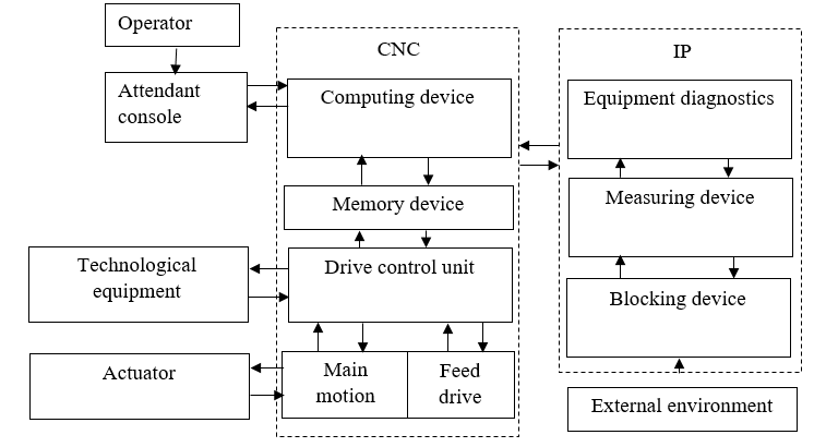
Figure 1–Block diagram of the machine control system
Conclusion
The paper presents the development of an automatic control system for the coordinated motion of the main motion drive and the feed drive of the machine, designed for the manufacture of parts of complex cutting configuration. The drives are driven by servos. In its composition, they have high-speed electric motors
References
- Петренко Ю.Н., Г.И. Гульков. Автоматизация типовых и промышленных установок. Тексты лекций / Петренко Ю.Н., Г.И. Гульков. - Мн.: БПИ, 1989 - 82 с.
- Фираго Б.И. Учебно-методическое пособие к курсовому проектированию по теории электропривода для студентов специальности 1-53 01 05 «Автоматизированные электроприводы» / Б.И. Фираго. - Мн.: БНТУ, 2005. - 126 с.
- Справочник технолога-машиностроителя. В 2-х т./ Под ред. А.Г. Косиловой и Р.К. Мещерякова. 4-е изд., перераб. и доп. - М.: Машиностроение, 1986. - 496с., ил.
- Соколов Н.Г. и Елисеев В.А. Расчёты по автоматизированному электроприводу металлорежущих станков. Учеб. Пособие для вузов по специальности Электропривод и автоматизация промышленных комплексов”. - М.: Высш. школа, 1969 - 296 с. с ил.
- Фираго Б.И. Теория электропривода: Учеб. пособие/ Б.И. Фираго, Л.Б. Павлячик. - Мн.: ЗАО “Техноперспектива”, 2004. - 527 c.
- Руководство по эксплуатации преобразователя частоты фирмы Delta Electronics серии UFD-S.
- Анхимюк В.Л., Опейко О.Ф., Михеев Н.Н. Теория автоматического управления. - Мн.: Дизайн ПРО, 2000. - 352 c. с ил.
- Петренко Ю.Н. Системы программного управления технологическими комплексами./ Ю.Н. Петренко. - Мн.:НП ООО «Пион», 2002 - 334 с. с ил.