
Abstract
Сontent
- Introduction
- 1. Timeliness of the topic
- 2. The purpose and objectives of the study, the planned results
- 3. Review of research and development
- 4. Overview of existing CAD
- 4.1 CAD GRACIA
- 4.2 CAD CATIA
- 4.3 CAD Autodesk AutoCAD
- 4.4 CAD AVEVA Plant
- 4.3 CAD AVEVA Diagrams
- 5. AVEVA Diagrams – vizio
- Conclusion
- List of sources
Introduction
Product designers’ productivity increase, design time reduction, improvement of quality of project development are prime problems, dealing with which defines the level of activation of the technical progress of society. The development of the computer-aided design (CAD) system is based on strong scientific and technical basis. These are contemporary computer equipment, new ways of presenting and processing the information, creation of new digital methods of solving engineering problems and optimization. The computer-aided design systems give an opportunity to develop design methodology on the basis of recent achievements on fundamental sciences, also it stimulates the development of mathematical model of designing of complicated systems and objects. Nowadays resources and methods for automation of routine operations such as preparing text documents, transformation of engineering drawings, imaging etc. are generally created and used.
1. Timeliness of the topic
One of the prominent objects of modern computer-aided design (CAD) systems is to rid the engineer of routine work and give the opportunity to concentrate on the creative process. Nowadays a big list of CAD systems are used, from small graphical programs to powerful specialized packs.
Against the background of market economy and active competition there is an especially pressing issue for businesses – the problem of regular updating the products, releasing new modifications of the present models to satisfy the demands of maximum consumers. The sphere of application of the computer-aided design (CAD) systems nowadays embraces various people’s activities – from furniture arrangement in a flat to designing and production of IC chips and modern space systems. Every type of problem of the engineering draughtsmanship imposes its own requirements on these products, but the biggest prevalence it got in mechanic engineering and architecture [1].
2. The purpose and objectives of the study, the planned results
For the development of the automated pipeline design subsystem, the AVEVA Diagrams design system was chosen
The main objectives of the study:
- analysis of the capabilities of existing CAD systems and highlighting their main positive qualities;
- identify the optimal set of further development of the pipeline editor in CAD CAD systems;
- justify the selected method and technological development of the pipeline editor.
Object of study: the process of developing a pipeline design automation module.
Subject of study: analysis of methods for creating pipeline design techniques.
3. Review of research and development
Designing is the process of creating a description necessary to build an object that does not yet exist in a given environment [2].
There are 3 main ways to implement the design:
- If the entire design process is human, then the design is called non-automated.
- Design, in which the interaction of man and machine occurs is called automated. Computer-aided design, as a rule, is carried out in the mode of human-computer dialogue based on the use of special communication languages.
- Designing, in which all transformations of the descriptions of an object and its functioning algorithm are carried out without human participation, are called automatic.
The set of project documents in accordance with the established list, in which the result of the design is presented, is called a project.
One of the most important design stages is the development of the technological part, including technological schemes. The schemes carry the basic characteristics of technological objects and automation systems, on the basis of which certain engineering decisions are taken at subsequent design stages. At the same time, it is extremely important to track all the changes made, check the relevance and integrity of the design data, and be able to make timely decisions in case of non-conformities. Routine operations should be automated as much as possible, since this will greatly reduce the time required for the execution of work, as well as provide quick access to the necessary data.
All this can be achieved with the use of computer-aided design. The most effective will be the use of software solutions that allow working at different stages of the project in a single engineering database. This solution is the program AVEVA PDMS, now supplemented by a new module – AVEVA Diagrams [3].
4. Overview of existing CAD
4.1 CAD GRACIA
Grace is a clothing design system, the complex of which includes a program for designing clothes that ensures the fastest possible turnover of models and high quality products, and is also successfully used in the production of all types of women's, men's and children's clothing, knitwear and fur products, hats, backpacks, tents, leather goods [4].
Sewing CAD GRACIA
provides comprehensive automation of all stages of design and technological preparation of the production of garments.
One of the advantages of the GRACE is that each developed model can be used in the future with subsequent modifications or it can serve as the basis for the development of a series of new models on its basis. For example, by changing the extensions along the lines of the chest, waist and hips, products of various silhouette shapes are obtained.
In grace, design (creation of a new model) begins with the development of an algorithm for developing a product design.
The system provides a block-modular principle of the structure of the algorithm. The algorithm is a set of actions, recorded
in a certain sequence, followed by execution in the system. When compiling it, the user can select an action that is represented
by one operator from the proposed list or enter it from the keyboard. A specialized programming language for creating a model
is logical and corresponds to the human perception of the actions described.
In the arsenal of this CAD there is an operator if ..., then ..., otherwise ...
, the presence of which provides the ability
to record knowledge in the form of an algorithm and transfer them to the system. Instead of the usual database, the designer
creates a knowledge base and thus, the systems become an intelligent assistant of the designer. For example, the system may
change the configuration of the sleeves of the sleeves, depending on the rate of planting material per centimeter of armhole
length; automatically design the number of tucks in the waist line, depending on their total solution.
As the algorithm develops, the product design is built. At the stage of completion of the algorithm, all the procedures are performed, and the result is displayed on the screen (Fig. 1) in the form of patterns of details of the necessary parameters, followed by the possibility of printing and cutting with an automatic cutting installation. When constructing a structure for typical figures, the system takes the values of dimensional attributes from the database.
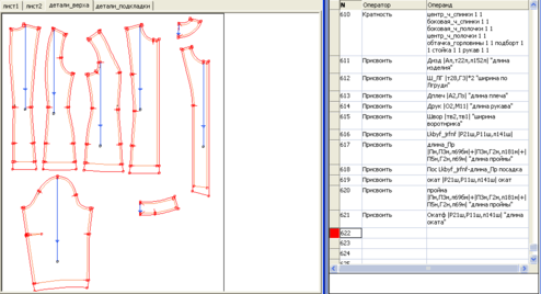
Figure 1 – Ready model in CAD GRACE
The principal difference is that in GRACIA all the preparation and planning processes are interconnected, that provides automatic execution of calculations for user-defined algorithms and formulas. The system issues calculation of direct production costs per unit of product.
4.2 CAD CATIA
CATIA (Computer Aided Three-dimensional Interactive Application) – this is an integrated automated system engineering design (CAD), technological preparation of production (CAM) and engineering analysis (CAE), which allows effectively solve all the tasks of technical preparation of production – from external (conceptual) design to issuing drawings, specifications, wiring diagrams and control programs for CNC machines [5].
CATIA's product portfolio currently includes over 300 functional modules that can be classified and grouped by the following parameters:
- platforms;
- areas of applicability (domains);
- configurations;
- individual products.
For programming in CATIA and creating custom applications, its base is used by CAA, RADE, Automation modules.
CAA (Component Application Architecture, CAA2, CAA V5) & ndash; This is a full-featured multi-level API for writing applications. all types under CATIA V5. CATIA applications can be divided into the following categories:
- embedded (embedded, they are the same CATIA AddIn) – add-ons loaded directly into CATIA\ENOVIA\DELMI;
- standalone;
- CMD-line – as a rule, various kinds of converters, validators, etc.;
- Interactive – everything up to creating your own CATIA-like environment.
RADE (Rapid Application Develpment Environment) & ndash; This environment allows you to properly build CATIA applications written using CAA. RADE is a set of programs and scripts run from the command line, It also has a & laquo; front-end & raquo; in the form of & laquo; add-in & raquo; to MS Visual Studio. After properly installing RADE, specific CAAs appear in the studio menu. points. An ALR license (or equivalent) is required for RADE to work.
CAA without RADE is more likely to be of theoretical interest, because the possibility of its practical use in this case is very doubtful.
CATIA V5 Automation & ndash; a set of Automation (OLE, COM, ActiveX, VB\VBA) objects representing a high-level API for CATIA V5. Main differences from CAA (Fig. 2):
- does not require installation of CAA and special license;
- relatively easy to use and allows you to solve a fairly large range of tasks;
- does not provide access to some of the functionalities available in CAA (for example: topological core, mathematics, direct access to the contents of features, etc.);
- the automation API is synchronized with the viewer (creating an array of 10,000 dots will take 100 times longer than with CAA) Allows working with Knowledgeware, writing internal macros and external extensions on any COM or .NET & ndash; supporting language.
Creo models can be deposited at Windchill server locations and exported to proprietary CATIA V5 formats of CATProduct assemblies and CATPart and CGR parts components. The export creates transformed Figure models (TIM) in the workspace. CATProduct is an assembly file format that contains links to CATPart component files and CATProduct subassembly files. CATPart is a part file format that contains exact and faceted geometry. CGR is a facet-only format representing parts and assemblies.
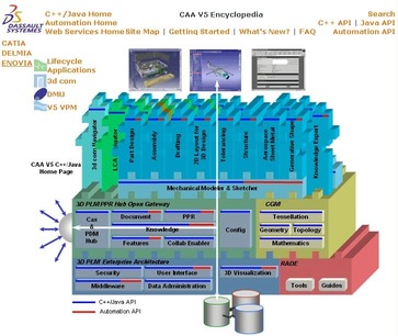
Figure 2 – CATIA Automation API Module.
Since CATIA implements a classic object-oriented approach, then input parameters (arguments) for calculations can be any geometric or non-geometric characteristics of the object with which the engineer considers it necessary to work: volume, mass, surface area, moment of inertia, material grade and others. Also, this CAD system has a tree structure, which greatly simplifies the work and allows you to quickly trace the geometry of the designed model, displays the sequence of technological operations, transitions and the cutting tool used at the same time. With this tree structure you can easily edit (change the geometry of the tool) and reproduce the necessary process.
Thus, in the engineer’s arsenal a tool appeared that provides the ability to store and use his professional knowledge.
4.3 CAD Autodesk AutoCAD
AutoCAD is a flexible development platform for specialized applications for computer-aided design. The open architecture allows you to tailor AutoCAD to specific user tasks. Examples of such adaptation can serve as a CAD based on Au toCAD for various branches of design, as well as thousands of add-ons developed by members of the Autodesk Developer Network [6].
ObjectARX programming environment is used to adapt and extend the functionality of AutoCAD and products based on it. She is Provides direct access to AutoCAD database structures, graphics and built-in command definitions. Using object-oriented C++ programming interfaces, developers can create applications for AutoCAD and other products in this family & ndash; eg AutoCAD Architecture, AutoCAD Mechanical and AutoCAD Civil 3D (Fig. 3).
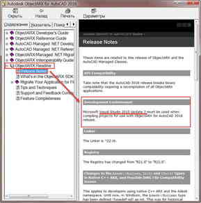
Figure 3 – Autodesk AutoCAD Programming Tools.
The Visual LISP application development system allows you to adapt the AutoCAD runtime environment by adding new functionality to the product.
The ObjectARX SDK also includes a managed API, often referred to as the AutoCAD .NET API. To adapt and extend the functionality of AutoCAD and products based on it can use any programming language that supports .NET. Direct access to AutoCAD database structures is provided. embedded command definitions and other internal program elements. The Microsoft Visual Basic .NET language (VB.NET) is easy to learn and use, and at the same time opens up a full range of ObjectARX capabilities for application developers. How to learn how to work with the interface of AutoCAD .NET, described in the online ru AutoCAD .NET Developer's Guide. ObjectARX SDK, in turn, has been tested over the years, but C++ programming implies the presence of reliable knowledge the developer of both the programming language itself and the algorithmization when working with 2D and 3D spaces.
The ActiveX interface allows you to access AutoCAD and automatically perform the necessary actions in it using the COM automation mechanism. Such applications are possible, for example, from standalone applications written in Microsoft Visual C++ or Microsoft .NET Framework, as well as from VBA-supported applications & ndash; such as Microsoft Office. In addition, the ActiveX interface can use add-ins for AutoCAD, created using Visual LISP, ObjectARX and AutoCAD .NET API.
4.4 CAD AVEVA Plant
AVEVA Plant & ndash; This is a set of integrated applications for the development of the circuit part of the project (technology, instrumentation, electrician) and create a 3D model of the object & ndash; general layout and detailed & ndash; on metal structures [7]. In the integrated line of AVEVA technologies for design, there are three main categories of solutions:
- Scheme Solutions & ndash; charts, diagrams, questionnaires, explications of process equipment and pipelines and other documents are created.
- 3D design & ndash; 3D models are created for all project disciplines, design errors are eliminated, and project / working documentation is issued.
- Control and management of data and technology changes.
- Individual products.
Main characteristics:
- integration of schematic and 3D data, which guarantees the exact correspondence of data at different stages of the project;
- flexibility in the choice of tools for the development of schemes, including technological;
- the fastest and most efficient system for error-free design, construction and reconstruction of industrial objects of any size and complexity;
- the possibility of geographically distributed design;
- tight integration with the engineering data management system to support the life cycle of the object as a whole.
Aveva PDMS has a wide range of customization capabilities and includes the PML programming language and the .NET API system, which allows you to adjust the operation of the system in accordance with the requirements of a specific user and to automate processes to the maximum PDMS integrates with all applications of the AVEVA Plant line and thus forms a unique system with wide possibilities for customization for designing industrial objects in a three-dimensional environment.
4.5 CAD AVEVA Diagrams
AVEVA Diagrams provides effective opportunities not only to quickly create schemes, but also to form these schemes. in the model database. This makes them easily available for use and storage in a structured manner as primary reference materials for all developers involved in the project [8].
Main characteristics (Fig. 4):
- Integrated tools & drawing sheet & raquo; Microsoft Office Visio provide a rich functionality environment.
- AVEVA Diagrams comes with a set of substrates and a library of symbols that represent the most common conditional. designations for schemes used in the design of industrial facilities and shipbuilding. It is also possible to create custom characters. Symbols used in schemas may have default parameter values. If necessary, you can select the mode of requesting certain values of parameters from the user.
- The ability to create diagrams consisting of several drawing sheets, while between individual sheets are set links. The same principle can be used to divide the existing scheme into sheets.
- Schemes can be performed on a substrate of general layout or plan.
Figure 4 –Main characteristics of AVEVA Diagrams.
(animation: 7 frames, 5 cycles of repetition, 62 kilobytes)
5. AVEVA Diagrams – vizio
Microsoft Office Visio & ndash; it is a professional solution for creating technical and business diagrams intended for systematization and visual presentation of various data, processes and systems. Microsoft Office Visio Professional Charts make it easy to visualize and exchange various information with the highest accuracy, reliability and efficiency, unattainable when using text and numeric data. Microsoft Office Visio Professional contains all the features of the standard release, as well as an extended set of templates and functions, including data visualization and data connection [9].
P & ID, PFD and HVAC charts are key documents that define the functional design of any design, ship or marine structures. They are a key part of the project activity and are still referenced and developed during the operation and maintenance phases.
AVEVA Diagrams provides a fast, effective and efficient solution for creating schematic diagrams. Another advantage is that, as the diagram is constructed, data is automatically created in the database of circuit models.
Thus, the information obtained can be effectively managed and easily accessed by any engineer who requires information and has the appropriate access rights. When designing diagrams, rules and automatic actions can help users create fully consistent diagrams, thereby avoiding costly downstream errors. When used as part of the integrated software AVEVA, AVEVA Charts Add P & ID data to the full project information model, exposing it to the full spectrum of AVEVA design, engineering, collaboration. and life cycle management technologies [10].
Conclusion
Based on the features of AVEVA Diagrams and the principles of its work, it follows that it is not possible to record data (created schemes) to the catalog with its subsequent use and modification, such as, for example, in CAD software GRACE. Therefore, AVEVA Diagrams is a special application in which, in order to automate the design process, you can create a catalog like GRACIA or CATIA.
This task is solved by creating a subsystem that will be implemented in the form of designing some type pipelines in AVEVA Diagrams.
This solution will allow you to automate and improve the level of the settlement-graphical method using formulas and dimensional signs. The main feature of the proposed technology is that with the help of operators in the form of The workflow constructor records the build process. Calculations and graphical constructions are performed. using recorded actions in the developed subsystem AVEVA Diagrams.
List of sources
- Application of automated design systems [Electronic resource]. – Access mode: https://pandia.ru/text/80/611/39607.php
- General information about the design. Types of CAD software [Electronic resource]. – Access mode: http://old.sapr–library.ru/biblio/ibm/contents/obsved.htm
- Alexandra Miroshnichenko. AVEVA Diagrams – we develop technological schemes, OVIK schemes and one-line electric circuits [Electronic resource]. – Access mode: https://sapr.ru/article/21575
- CAD-system GRACIA [Electronic resource]. – Access mode:https://starer.ru/program-for-cutting-and-sewing-free-technical-drawing-software/
- CAD-system CATIA [Electronic resource]. – Access mode: http://bourabai.ru/cm/catia.htm/graphics/graphics/dm/cad.htm
- CAD-system Autodesk AutoCAD [Electronic resource]. – Access mode: https://www.autodesk.ru/autodesk-developer-network/software-platform-russian/develop-autocad
- Overview of CAD-system AVEVA Plant [Electronic resource]. – Access mode: https://www.aveva.com/~/media/Aveva/Russian–RU/Brochures/AVEVAPlant.pdf
- Overview of CAD-system AVEVA Diagrams [Electronic resource]. – Access mode: https://www.aveva.com/~/media/Aveva/Russian–RU/Brochures/Diagrams.ashx
- Easy creation of P&ID, PFD and similar diagrams tha fully integrate with the model database [Electronic resource]. – Access mode: http://www.vizio.cz/download/AVEVA_DiagramsInfo.pdf
- Product description Microsoft Office Visio [Electronic resource]. – Access mode: https://itpro.ua/product/microsoft–visio–professional–2016