
Contents
- Introduction
- 1. Earth fault in three-wire networks of 6–10 kV
- 1.1 Earth fault
- 1.2 Arc short to ground
- 1.3 Earth fault current compensation
- 1.4 Earth fault relay protection
- 2.Dynamic Model of an Oscillographic Galvanometer
- Conclusion
- References
Introduction
At industrial enterprises, 6–10 kV networks are made with isolated neutral. In these networks, earth faults are not short, therefore, with such damage, operation can continue for some time. However, during faults, the voltage across the insulation of intact phases rises and surge surges occur during faults through an arc. Overvoltages can cause breakdown of insulation in another phase, which leads to the occurrence of large currents of double circuit to earth. Arc can cause burnout of cables and iron motors. To assess the effects of fault currents on the earth, the need for their compensation, you need to know the magnitude of the fault currents. This determines the practical relevance of the work. In design, fault currents are determined by calculation without taking into account transients that cause surge voltages. The scientific relevance of the work is determined by the need to develop methods for experimental analysis of fault currents. In this regard, it is necessary to solve the following problems: to digitize the waveforms of currents and voltages of metal and arc faults, to develop a dynamic model of the oscillographic galvanometer (OG), which was used in the oscillography, to correct the dynamic error of the oscillography, to develop a mathematical model of the current of the metal fault to ground.
1.Earth fault in three-wire networks of 6–10 kV
1.1 Earth fault
The power supply system of 6–35 kV distribution networks is an isolated neutral system. Electric energy is transferred to consumers via a three-wire system using cable or overhead lines. This mode of operation of the neutral makes it possible to increase the reliability of the supply of consumers with some types of damage in the electrical networks.
Figure 1.1 – The metal ground-fault of phase C (animation: 9 frames, 5 cycles of repeating, 178 kilobytes)
In distribution networks with isolated neutral, a short circuit of one of the phases to earth does not lead to a short circuit and in a large number of cases does not require disconnection of the damaged section. Linear voltage remains unchanged, the same as before the faulted phase is shorted to ground. In cases where a single-phase fault occurs in distribution networks with an isolated neutral, processes appear that affect the operation of the electrical network as a whole. The voltage of the phase at which the damage occurred, despite the type of fault, tends to zero. At times when the measuring devices show that the voltage in the phase is zero, they say that it is full ground
, and short circuit is called metallic
.
In case of a metal earth fault, at the initial moment, a transient process takes place, which lasts about a quarter of the period, that is, 5 ms, after which the steady state occurs. At these times, large inrush currents and pulsed overvoltages are observed. Since the duration of the transition mode is not long, the inrush current does not cause overheating of the damaged cable. However, overvoltages can cause a cable insulation failure at any other point in the network. This kind of double circuit is close to a two-phase short circuit and in case of failure of relay protection, it will cause unacceptable heating at the points of short circuit. In other words, a single-phase earth fault in a distribution network with an isolated neutral is dangerous by the development of a two-phase short circuit.
1.2 Arc short to ground
Arc faults in operation usually occur less frequently than earth faults. With this short circuit, transients occur with each ignition or attenuation of the arc. Capacitive currents of single-phase earth faults in 6-10 kV networks with isolated neutral are relatively large (tens, hundreds of amperes), fault arcs tend to burn stably for a long time, affecting insulation, current-carrying and magnetically conductive network elements. All this creates the conditions for the development of accidents-transition of single-phase earth faults into two-or three-phase short circuits. To protect the network in the event of prolonged burning of arcs of capacitive currents, it can be carried out by switching to the mode of operation of networks with resonantly grounded neutral.
Due to the large amount of current, overheating becomes greater, but the overvoltage will be less. This is due to the fact that deionization almost does not occur, arc burning occurs stably, and current surges when the arc appears and breaks off at a low speed. At low currents, the overhang will be less and the overvoltage more.
Arc faults are more dangerous than metal, since surge overvoltages occur not only in the initial period of time, but all the time. In addition, an arc can lead to burnout of the cable and iron of the motor.
Arc faults have a negative effect on surge arresters. In the case of a metal circuit, the arrester reduces the surge voltage only once in the initial period. And at the time of the arc fault, the arrester is triggered all the time, so it overheats. There were cases of failure of the arrester during an arc fault to earth.
1.3. Earth fault current compensation
The value of the capacitive earth fault current in networks with isolated neutral is reduced to the value at which the arc goes out at the place of damage. These actions are carried out when the neutral of the generator or transformer is grounded through arc suppression reactors, inductive resistance. Most often, arc suppression reactors are used, which consist of a core and a winding located in a casing filled with transformer oil. By varying the number of turns or the core gap, the inductance of the reactor L is regulated. Compared to the value of the inductive resistance, the resistance value is very small.
For a long time, a system with a phase closed to earth can work when compensating for capacitive current at the point of fault by inductive current. Moreover, the voltage value at all points of the network is unchanged as in a system with isolated neutral. compensation efficiency indicator is the ratio of the number of earth faults that did not develop in the short circuit to the total number of faults.
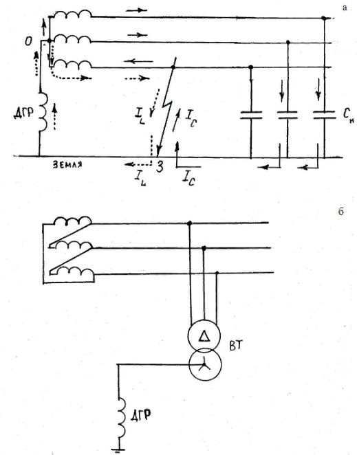
Figure 1.2 - Connecting the GDR when connecting the supply transformer to a star with zero (a) and a triangle (b)
Systems with capacitive current compensation, the numerical value of this ratio is 0.6–0.9, and in systems with isolated neutral 0.3. Relay protection against earth faults is not required in compensation networks. Relay protection in such networks is designed to disconnect lines, transformers and generators, as well as electric motors connected directly to the network. An exception is 3-35 kV systems with an increased risk of equipment maintenance, in which earth faults must be selectively disconnected. These include power supply systems for mines, open pit mines, peat mines, and others. Compensation for capacitive currents has the following qualities that are advantageous for operation: it reduces the current through the fault location to a safe value, thereby ensuring reliable extinguishing; facilitates storage requirements; reduces the speed of voltage recovery in the damaged phase, as a result of which the probability of re-ignition of the arc and the occurrence of switching voltages is small; while maintaining a stable arc, it reduces the likelihood of a short circuit to earth in a multiphase fault, etc.
Compensation efficiency depends on the perfection of arc suppression reactors. The compensation efficiency with a constant reactor setting is 0.6. and when using a reactor with magnetization and automatic quick adjustment of 0.9.
The fault current is more than 10 A in all systems with a voltage of 35 kV, it is necessary to install an arcing reactor. In systems with a voltage of 3–10 kV, in which there are power lines with metal and reinforced concrete supports, where the magnitude of the fault current is more than 10 A. Compensation of the capacitive earth fault current should be applied at normal current values in systems that do not have reinforced concrete and metal supports on overhead lines: more than 30 A at a voltage of 3–6 kV; more than 20 A at a voltage of 10 kV; more than 15 A at a voltage of 15–20 kV; more than 5 A in circuits with a voltage of 6–20 kV generator-transformer blocks (at generator voltage). For earth fault currents of more than 50 A, at least two earthing arcing reactors are recommended. The reactor can be included in the neutral of one working transformer, which at the same time receives additional load. They allow the inclusion of a reactor with a capacity equal to 50% of the power of the transformer, provided that it will work with the highest compensation current for no more than 2 hours.
1.3. Earth fault relay protection
To protect the lines from short-circuit current to earth, special protections are used that respond to current and zero sequence voltage. The need to install a zero sequence protection on the lines is caused by the fact that a common phase fault is a single-phase short circuit. Protection reacting to current and zero-sequence voltage is much simpler and has several advantages compared to current protection reacting to full phase currents. This type of protection is performed in the form of MTZ and TO.
The essence of this method is that any 3-phase asymmetric system of current or voltage vectors can be replaced by the sum of 3 symmetric systems.
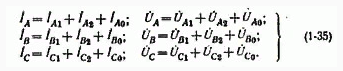
Figure 1.3 - Equations of 3 symmetric systems
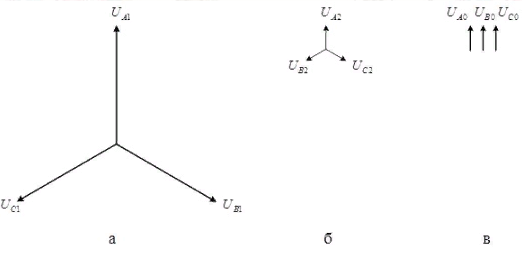
Figure 1.4 - Voltage systems of direct (a), reverse (b) and zero (c) sequences
Based on Fig. 1.4, we can conclude that:
- Direct sequence vectors rotate counterclockwise, follow each other in alternation A–B–C;
- The reverse sequence vectors rotate in alternation A–C–B;
- Vectors of zero sequence coincide in phase and direction.
In the normal symmetric mode, as well as in a symmetrical 3-phase short circuit total currents and voltages are equal to the current and voltage of the direct sequence, the components of the negative and negative sequence are equal to zero. The components of the negative sequence appear in the network for any asymmetry: 1 phase short circuit, 2 phase short circuit, phase failure, unbalanced load .
From the theory of symmetrical components during earth faults, it is necessary to distinguish the following provisions: components of the zero sequence appear only at short circuit to the ground (single-phase and 2-phase), as well as when one or two phases break. With interphase short circuit without earth (3 and 2 phase) currents and voltages of zero sequence are absent.
With a single-phase short circuit zero sequence current at the fault location is 1/3 of the short-circuit current at the same point and coincides with it in phase, and the voltage of the zero sequence is 1/3 of the geometric sum of the voltages of the undamaged phase.
Thus, in the place of short circuit a current equal to the sum of the zero sequence currents I0 of all three phases passes to the ground, which is the actual fault current IK = 3I0. This current is directed through the earth to the grounded neutrals of the transformers and returns to the phases of the network, and the appearance of zero sequence currents is possible only in the network where there are transformers with grounded neutrals.
If the transformer has a star delta winding connection, then an earth fault on the side of the delta does not cause zero sequence currents on the side of the star. If networks of different voltages are connected by a transformer having a star star connection circuit with grounded zero points of both windings, a ground fault in the network of one star causes the appearance of zero sequence currents in the network of the second star. In the presence of autotransformers connecting the network of two voltages, a ground fault in the network of one voltage causes the appearance of zero sequence currents in the network of another voltage.
2.Dynamic Model of an Oscillographic Galvanometer
Oscillography is carried out by a light beam oscilloscope. Light-beam oscilloscope belong to direct action devices. Registration is carried out by an ordinary light ray or ultraviolet ray on a special photosensitive medium that does not have a diagram grid.
The advantage of the Light Beam Oscilloscope in comparison with the widely used electron beam oscilloscope:
- Simplicity and convenience of obtaining OS registration documents, especially when registering on UV-type media;
- Possibility of simultaneous registration on a single medium of a multitude (several tens) of the studied dynamic processes.
When decoding the waveforms, any time intervals of the process under study are determined and currents are determined at each moment of time that the experimenter is interested in. To establish the scale along the time axis in light-beam oscilloscopes, a time stamp is used. Most often these are special electromechanical devices that draw vertical lines on the light source at certain intervals, for example 0.2; 0.02 s, etc. Counting the number of lines between the necessary points of the recorded curve and multiplying this purely by the time stamp scale, the value of the time interval is determined.
Miniature magnetoelectric measuring mechanisms called oscilloscopic galvanometers (OG) are used as measuring mechanisms in the Light Beam Oscilloscope. The main units of the beam-beam oscilloscope is a block with oscillographic galvanometers, an optical system, a rotary mechanism, and a time lock. Let us briefly dwell on the main nodes of a light-beam oscilloscope. In a light-beam oscilloscope, an oscillographic galvanometer insert is used. The galvanometer-insert is a moving part of the magnetoelectric measuring mechanism (moving frame on braces) installed in a non-magnetic metal casing with pole tips made of soft magnetic material. Usually the outer diameter of the casing is 6mm. The galvanometer-insert is placed by the experimenter in the air gaps of the magnetic circuit of one large permanent magnet. A magnetic block of type M1062 has grooves in the magnetic circuit to accommodate simultaneously 12 different exhaust gases and a pitch of 9 mm.
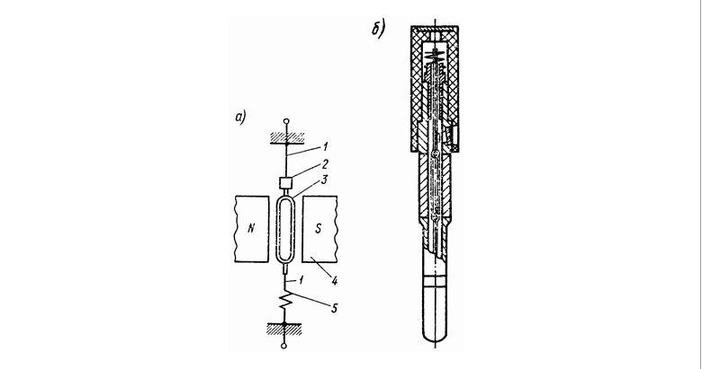
Figure 2.1 - Diagram of the device (a) and design (b) of the magnetoelectric oscillographic galvanometer
The main requirements for exhaust gas and have a significant impact on their design:
- The possibility of large frequency ranges, therefore, possibly a large frequency of natural oscillations of the moving part F0;
- Sufficiently high sensitivity to current S1;
- Perhaps a smaller insert diameter to increase the number of simultaneously installed exhaust gas.
Fig. 2.2 shows the design of the moving parts of the most extensive exhaust frames. Fig. 2.2 shows the moving part of the exhaust gas with magnetically inductive winding or liquid soothing. The torque, as in the case of conventional magnetoelectric mechanisms, is created by the interaction of the current I in the frame 1, stretched on blocks 2 by means of braces 3 and a permanent magnet field. The moment of tranquility is created by the interaction of the field of the permanent magnet and current Iusp, which is formed in the circle of the frame from the EMF, inductive in the frame when it moves. It is obvious that the current Isp, and, accordingly, the moment of damping, will be dependent upon winding damping, primarily on the resistance of the circuit with the frame. The optimum damping moment is considered to be the damping moment, which provides the most efficient exhaust gas frequency band for a given permissible non-linearity of the amplitude-frequency characteristic.
The nonlinearity of the amplitude-frequency characteristics of the exhaust gas with winding damping should be no more than ±5% in the frequency range from 0 to 0.6F0 (±10% in the frequency range from 0 to 0.75F0).
Calming exhaust gas is typically characterized by a coefficient called the calming stage. Optimal calming is obtained at 0.7. From the above it follows that for exhaust gas with winding quieting, the external resistance value should be indicated in the passport, at which the optimal value is ensured, from which the most possible working frequency band follows.
With liquid soothing, the moving part of the exhaust gas is filled with a special liquid. Typically, such exhaust gases have winding damping, but liquid damping prevails over winding damping, and therefore, the external resistance of such exhaust gases can be any number of cases. The viscosity of the fluids used depends on the ambient temperature. Therefore, in modern light-beam oscilloscopes, temperature control.
Fig. 2.2 shows the moving part of the exhaust gas with magneto-inductive frame calm. Frame 1 is wound on an aluminum plate 5 with lapels for stretch marks. When the frame moves around the plate, eddy currents appear that interact with the field of the permanent magnet and create a moment of calm. Frame damping always prevails over winding damping, and therefore exhaust gas with frame damping, as well as exhaust gas with liquid damping, can work at the optimum value regardless of the value of the external resistance of the galvanometer.
It is not hard to notice that the plate during frame soothing significantly increases the moment of inertia of the moving part of the galvanometer and worsens its frequency features. In some light-beam oscilloscopes of previous releases, in addition to the reaction of the signal under study, it was also possible to visually observe this signal on a specially installed. In such oscilloscopes part of the beam of light that is beaten off from the exhaust gas mirror hits the mirror drum B, which rotates at a constant speed. It is not hard to see that when the drum rotates, there is an angle of incidence to the beam on each face of the drum. It turns out that the spot created by the light beam moves along the screen, creating in the same way a temporary scan of the signal under study.
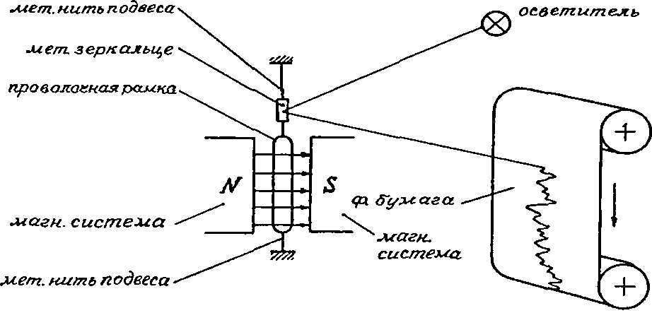
Figure 2.2 - Schematic diagram of the optical device of a light-beam oscilloscope
When decoding the waveforms, any time intervals of the process under study are determined and currents are determined at each moment of time that the experimenter is interested in. To establish the scale along the time axis in light-beam oscilloscopes, a time stamp is used. Most often these are special electromechanical devices that draw vertical lines on the light source at certain intervals, for example 0.2. Counting the number of lines between the necessary points of the recorded curve and multiplying this purely by the time stamp scale, the value of the time interval is determine.
Conclusion
The method for predicting capacitive currents used in design in networks of 6–10 kV does not provide objective information about the magnitude of currents and especially about transients. To justify the need and evaluate the effectiveness of compensation of earth fault currents, it is necessary to perform experiments on metal and arc faults. Oscillographic galvanometers introduce a dynamic error in the results of oscillography. To compensate for it, it is necessary to perform the correction of measurements, considering the galvanometer as an aperiodic link of the first order. The mathematical description of the process of metal earth fault is proposed to be carried out in stages. In steady state, the process of changing current is represented as a Fourier series. After subtracting this process from the corrected waveform of the fault current, the transient process should be approximated by the sum of the exponentials and exponentially sinusoidal functions. The mathematical description allows you to develop a dynamic network model in the form of elementary links, as well as perform their parametric identification.
References
- Справочник по электроустановкам высокого напряжения / Под ред. И. А. Баумштейна, В. М. Хомякова: Энергоатомиздат, 1989. – 656 с.
- Правила устройства электроустановок: Энергоатомиздат, 1985. – 640 с.
- Правила устройства электроустановок:
Форт
, 2009. – 704 с. - Ф. А. Лихачев. Замыкания на землю в сетях с изолированной нейтралью и с компенсацией емкостных токов: Энергия, 1971. – 152 с.
- Б. Н. Неклепаев, И. П. Крючков. Электрическая часть станций и подстанций: Энергоатомиздат, 1989. – 608 с.
- Э. Г. Куренный, Е. Н. Дмитриева, Н. Г. Вальков. Динамические погрешности осциллографирования электроэнергетических процессов и их коррекция // Энергетика и электрификация. – 1997.
- Н. В. Чернобровов. Релейная защита: Энергия, 1971. – 624 с.