
Aleksey Gorbunov
Electrotechnical Faculty
Department of Program Control Systems and Mechatronics
Speciality Microprocessor-based renewable energy management systems
Optimization of photovoltaic installation modes
Scientific adviser: Senior Lecturer, Chernikov Vadim Gennadevich
Abstract
Content
- Introduction
- 1. Relevance of the topic
- 2. The purpose and objectives of the study
- 3. Description of autonomous photovoltaic installation
- 3.1 Selection (justification of use) as the main control unit of the STM32F4 DISCOVERY debug board
- 3.2 Block diagram of an autonomous photovoltaic installation
- 4. Development of a consumer management system based on the STM32F4 DISCOVERY debug board
- 4.1 Hardware implementation of a consumer management system
- 4.2 Software implementation of a consumer management system
- 5. Results of practical tests of the developed control system
- Conclusions
- List of sources
Introduction
The use of photovoltaic plants for the production of electricity allows you to comprehensively solve the current issues of energy supply, environmental protection and saving of fossil energy sources.
1. Relevance of the topic
One of the measures aimed at optimizing and improving the efficiency of the photovoltaic installation is the creation of a consumer management system. For this purpose, the parameters of the structural elements of the stand-alone photovoltaic installation were calculated for given power consumers and the insolation level for a given area, the hardware of the control system of the stand-alone photovoltaic installation was developed and created, and, using the model-oriented programming method, the consumer management algorithm was developed and implemented.
2. The purpose and objectives of the study
The object of development and research is an autonomous photovoltaic installation.
The purpose of the study is to develop and create a consumer management system based on a microcontroller to optimize the operation of an autonomous photovoltaic installation.
Research and development methods are based on the general principles of industrial control systems, industrial electronics, computational methods and the use of modern software packages.
3. Description of autonomous photovoltaic installation
An autonomous photovoltaic installation (Fig. 1) is a photovoltaic system that is not connected to the central power grid and consists of solar panels that convert solar energy to electricity, and a battery system that stores this energy [1]. A charge controller that prevents deep discharge and overcharging the battery, and an inverter that converts direct current to alternating current can also be installed. [2]
Figure 1 – Autonomous photovoltaic installation. Animation: 6 frames, 98,4 kB
3.1 Selection (justification of use) as the main control unit of the STM32F4 DISCOVERY debug board
In this work, the task was to implement consumer management to optimize the operation of an autonomous photovoltaic installation. It was decided to use a microprocessor control system, where the STM32F407 microcontroller, available on board the STM32F4 DISCOVERY debugging board, serves as the main computing and control unit. This decision was made for the following reasons [3, 4]:
- optimal computing capabilities of the microcontroller for solving the problem of controlling an autonomous photoelectric installation;
- there is a reserve of computing power, which will further expand the capabilities of the control system;
- relatively low cost;
- due to its small size, the debug board has a fairly high degree of integration, which allows you to implement the final control system unit with minimal dimensions in comparison with using a PC.
3.2 Block diagram of an autonomous photovoltaic installation
The structural diagram of an autonomous photovoltaic installation (Fig. 2) can be conditionally divided into two parts: power and control system. In the power section, electricity is generated by the solar panel, accumulated in batteries, and transmitted to consumers.
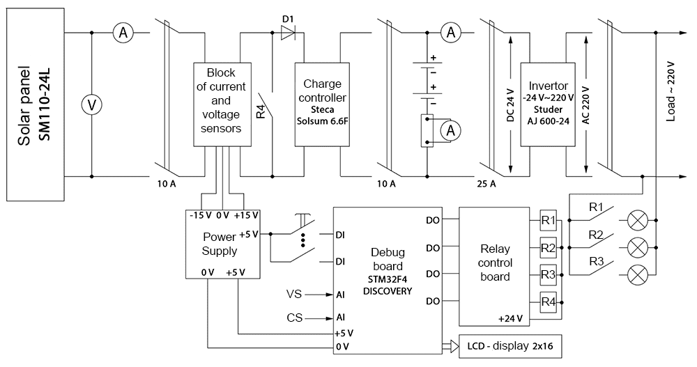
Figure 2 – Block diagram of an autonomous photovoltaic installation
The control system includes current and voltage sensors, a STM32F4 DISCOVERY debug board, a relay control board, and an operator panel.
4. Development of a consumer management system based on the STM32F4 DISCOVERY debug board
The control system implements the following principle: evaluating the short circuit current of the solar panel using the current sensor CS1, you can determine the density of solar energy, and, based on this density, estimate the maximum power of the photovoltaic installation. It uses the fact that the short circuit current is proportional to the density of solar energy [5]. By calculating the power consumed by the battery based on the current power consumption of the installation, we can estimate the difference between the maximum power of the photovoltaic installation at a given light and the power consumed by the battery. This difference shows the power reserves, which in the future allow us to determine how many consumers can be connected to the output of an autonomous installation in order to ensure its operation as close to the maximum power point as possible. The advantage of this approach is the possibility of optimizing the operation of the photovoltaic module without the use of a light sensor. The consumer management algorithm is presented in Figure 3.
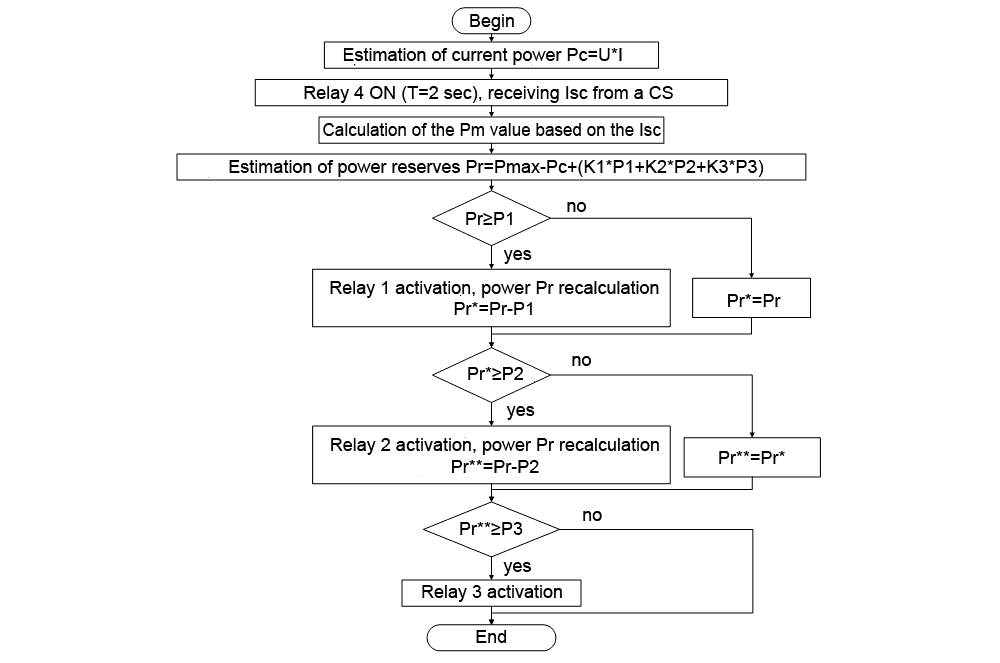
Figure 3 – Consumer Management Algorithm
4.1 Hardware implementation of a consumer management system
In practice, when a load is connected to a microcontroller, a problem arises that the microcontroller, as a rule, cannot provide the power necessary for the normal operation of an external load.
To implement the control of relay elements, a control circuit was developed using an assembly of Darlington ULN2003 composite transistors [6] and PC814 optocouplers [7].
The control circuit of one channel is shown in Figure 4.
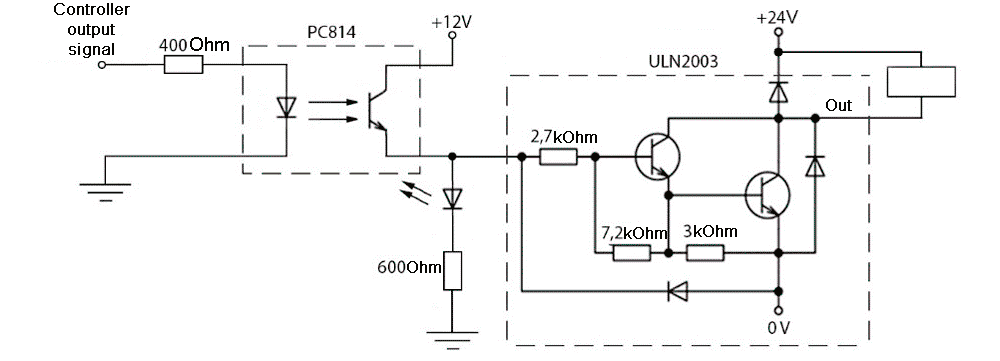
Figure 4 – Relay control circuit
This implementation allows low currents from the outputs of the microcontroller to control powerful relays (12 or 24 V). Optical isolation is implemented to protect the microcontroller in the event of a breakdown of the ULN2003 chip.
4.2 Software implementation of a consumer management system
The consumer management system software was developed using model-oriented programming using the Matlab application package, its Simulink graphical simulation environment and the Waijung Blockset extension package [8]. The block diagram of the control system in the Matlab package is shown in Figure 5.
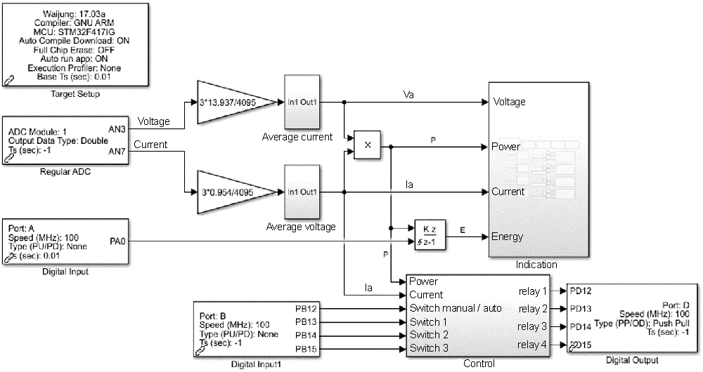
Figure 5 – Block diagram of the control system in the Matlab package
Analog signals from voltage and current sensors are transmitted to the ADC of the microcontroller, read out and digitized using the Regular ADC block (Fig. 6), normalized by the corresponding coefficients and transmitted to the subsystem for calculating the average value. The averaging period is equal to one second, while for the time of calculating the average value in the subsequent averaging period, the current average value is stored in the memory element.

Figure 6 – Model for calculating the average value of pulse signals from sensors
After averaging, the values of current power and generated energy are calculated. The obtained data of current, voltage, power and energy are transmitted to the display system. Current and power data, as well as signals from the operator panel, are transmitted to a subsystem that implements a control algorithm and generates control signals for relay elements.
In the display subsystem (Fig. 7), the data of the photovoltaic installation are converted into a string data format, stored in a buffer memory and then transferred directly to the LCD display.
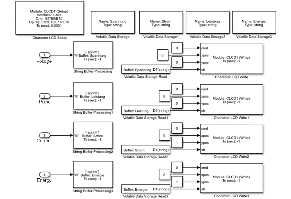
Figure 7 – Software model for displaying system parameters
In the control subsystem (Fig. 8), current measurement and calculation of maximum power are performed, the order and duration of all measurement processes and the duration of one control system cycle are formed. Also in this system, an operator panel control algorithm is implemented that excludes the simultaneous operation of manual and automatic control system operation modes.
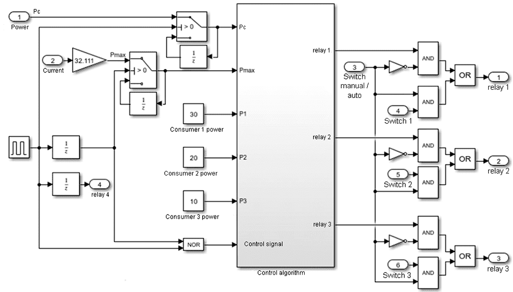
Figure 8 – Consumer Management System Software Model
In the subsystem of the control algorithm (Fig. 9), a phased assessment of the power reserve and the ability to connect consumers based on their priority, on the basis of which control signals are formed to connect consumers.
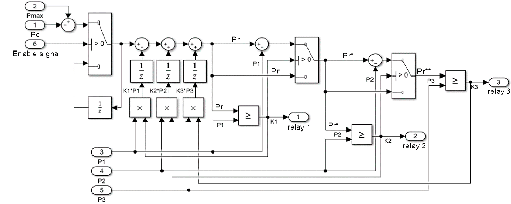
Figure 9 – Software model for generating relay control signals
Figure 10 shows the timing diagram of one cycle of the control system. The current and maximum capacities are measured sequentially for two seconds, and then for the remaining time of one period, the power reserves are evaluated and transferred to the control system.
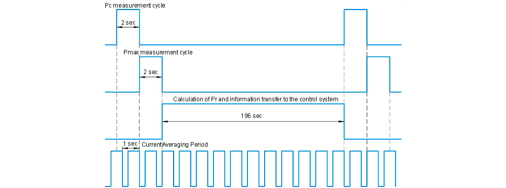
Figure 10 – Timing diagram of one cycle of the control system
On this, the development of the hardware and software parts of the control system was completed.
5. Results of practical tests of the developed control system
During the tests of the developed control system, the current (Fig. 11) and voltage (Fig. 12) waveforms of the solar battery were obtained when the battery was charged, with a 14 W consumer switched on and with a 21 W consumer switched on.
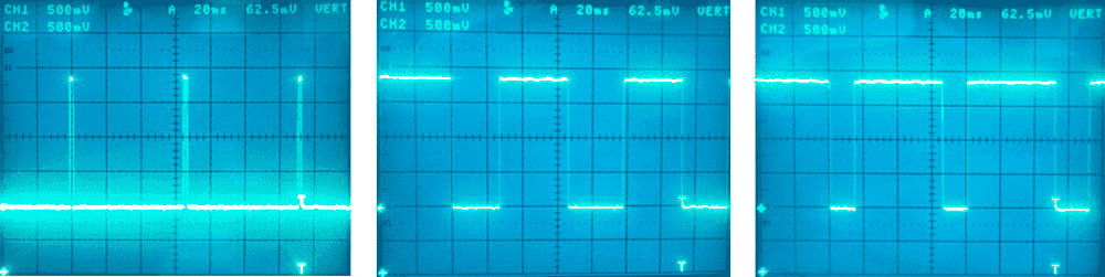
Figure 11 – Current waveforms
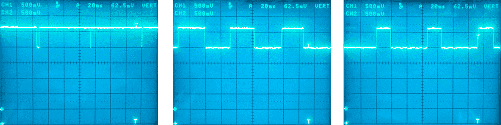
Figure 12 – Voltage waveform
Сonclusions
Thus, thanks to the created control system, the operation of an autonomous photovoltaic installation was optimized, as a result of which its efficiency increased. When writing this essay, the master's work is still under development. Final completion: June 2020. The full text of the work and materials on the topic can be obtained from the author or his leader after the specified date.
List of sources
- Фолькер Куашнинг Системы возобновляемых источников энергии. Технологии. Расчеты: Учебная литература. Изд-во Фолиант, 2013. – 432 p.
- Technisches Anwendungshandbuch Nr.10 Photovoltaikanlagen – ABB, 2011. – 116 p.
- Journal «Компоненты и технологии» [Electronic resource] – Access mode: http://www.kit-e.ru/ (date of the application 19.08.19).
- STM32F4DISCOVERY datasheet [Electronic resource] – Access mode: https://www.st.com/en/evaluation-tools/stm32f4discovery.html (date of the application 20.08.19).
- В. В. Елистратов, Е. С. Аронова Солнечные энергоустановки. Оценка поступления солнечного излучения: Учебное пособие. СПб. Изд-во СПбГПУ, 2012. – 164 p.
- ULN2003 7 channel load driver Electronic resource] – Access mode: http://hardelectronics.ru/uln2003.html (date of the application 15.09.19).
- PC814 optocoupler for use in AC circuits [Electronic resource] – Access mode: http://www.w-r-e.de/robotik/data/opt/pc814.pdf (date of the application 12.09.19).
- Waijung Blockset [Electronic resource] – Access mode: http://waijung.aimagin.com/ (date of the application 20.10.19).