


Investigation of the causes of damage to insulation transformers
Content
- Introdution
- 1. Damage to VT due to ferroresonance
- 2. Damage to VT as a result of overexcitation
- References
Introdution
In networks of 6–35 kV, an abnormally high breakdown rate of insulation control voltage transformers (TNKI) is observed. According to some reports, the annual damage to these voltage transformers (VT) is 7–10% of all installed, and the average service life does not exceed 3-5 years [1]. Despite the low cost and small weight and size indicators of VT perform quite important functions. They provide insulation control, lowering the high voltage to the values necessary to power the automation circuits, relay protection, electricity meters. In a modern market economy, the latter function of VT is extremely important. In addition, there are cases when damage to the VT was accompanied by its ignition and fires in switchgears. All this determines the relevance of the study of the causes of damage to TNCI.
The purpose of this study is to determine the causes of damage to TNCIs, evaluate the effectiveness of measures aimed at improving the reliability of these TNs.
1. Damage to VT due to ferroresonance
The main reason leading to TNCI damage is the existence of ferroresonance phenomena in the network, as a result of which currents many times exceed the nominal values pass through the HV windings [2, 3]. The ferroresonance mode is characterized by the equality of the inductance of the VT and the capacitive resistance of the network wL = 1/wC. Moreover, this equality can be fulfilled both on the main frequency of the network, and on the higher and lower harmonic components. Note that VT damage only occurs with subharmonic ferroresonance, and FRP at frequencies of 50 Hz and higher does not lead to VT damage [2].
A necessary, but not sufficient condition for the emergence of a ferroresonance regime is the presence of asymmetry in the network, which leads to the appearance of a neutral bias voltage. The main type of asymmetry in 6-35 kV networks is single-phase earth faults (OZZ), so it is advisable to study the processes during OZZ and its elimination. To solve this problem, a model of a network segment was created in the MATLAB package, which allows you to study the behavior of the network in all kinds of transients. First of all, these include processes with single-phase arc faults (ODZ) through an intermittent arc, processes during disconnection or self-elimination of the OZZ.
Metal short circuit and short circuit through a stable arc are not much different from each other in terms of their effect on VT. The currents in the HV windings under these conditions do not exceed permissible values and are not dangerous. Significant currents can occur after a short circuit is closed. Such processes can be accompanied by excitation of ferroresonant oscillations associated with the discharge of the zero-sequence capacitance of the network through the grounded windings of the HV transformers. Depending on the initial conditions and the ratio of the parameters of the network, the FRF can be of a fading or undamping nature.
The estimated network equivalent circuit is shown in Fig. 1. In the equivalent circuit, the supply transformer is represented by the EMF source E, the phase leakage inductance Li, and the resistance Ri. The network is reflected by the concentrated phase SF and interphase SMF capacitances, the active resistance Rп, simulating the active conductivity of the line to the ground.
Image 1 – The design scheme of the network under study in the mode of ODZ
(the animation consists of 8 frames with a delay of 500 ms between frames, the number of playback cycles - 3, size - 20 kilobytes)
In this paper, the operating modes of VTs of the NTMI-6-66 and NAMI-6-95 types are considered. The substitution schemes for these VTs are shown in Fig. 2 [3]. In the equivalent circuit, Lm is the resulting nonlinear inductance of the magnetizing circuit, R1 is the primary resistance, Rb is the ballast included in the open triangle winding to suppress ferroresonance, Ltn is the zero-sequence transformer inductance (FC).
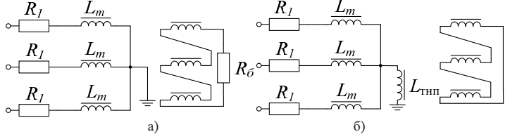
Image 2 – The equivalent circuit of TN type NTMI-6-66 (a), NAMI-6-95 (b)
Operational experience shows that significant damage to TNCIs is typical for networks with low earth fault currents (1–10 A) [4]. It is with these ratios of VT inductance and network capacity that undamped ferroresonance becomes possible. As an example in fig. Figure 3 shows the calculated current curves in the winding of the HV transformer during ferroresonance arising from the disconnection of the OZZ. The currents in this mode exceed the thermal resistance current of the winding, which is 0.3 A. The long-term existence of such a regime will certainly lead to the thermal destruction of the HV winding.
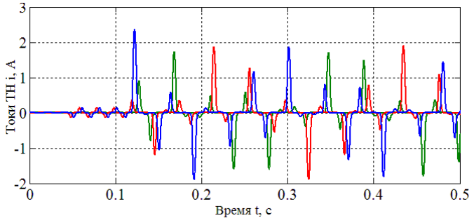
Image 3 – The calculated current curves in the HV winding during ferroresonance arising from the disconnection of the OZZ. Sf = 0.5 uF
As a result of numerous calculations, it was found that for one set of NTMI-6 VTs, the zone of existence of stable ferroresonance is in the range of phase capacitance in the range 0-1.5 μF. This is equivalent to a capacitive current of 0–5 A. In order to bring the mathematical model as close as possible to a real network, the calculations took into account the possible asymmetry of the magnetization curves of the TNCI phases, network capacities, and the deviation of the source voltage from the nominal one.
As the simplest and cheapest method of suppressing ferroresonance, it is worth highlighting the inclusion of a resistor of 25 ohms in the winding of an open triangle [2]. The action of the resistor is to bypass the non-linear magnetic shunt of the VT with a small resistance and create additional active losses in the zero sequence circuit. In fig. Figure 4 shows the calculated current curves in the HV winding for the case of suppression of ferroresonance by a 25 Ohm resistor in an open triangle winding. The curves show that after connecting the resistor, the currents in the winding begin to decay, which indicates the suppression of ferroresonance. We add that the FRF occurrence algorithm and network parameters are similar to the case shown in Fig. 3.
It is widely known that a 25 Ohm resistor in an open triangle winding is low efficiency in the fight against ferroresonance. This judgment is mainly based on operating experience. Practice shows that thermal damage to the HV winding, which occurs when there is an OZZ in the network, is possible both with the ballast resistor connected and in its absence. In [5], on the basis of a natural experiment, it was found that with earth faults through an alternating arc, a resistor of 25 Ohms does not prevent damage to the TNCs.
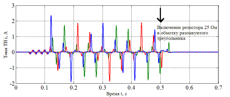
Image 4 – The calculated current curves in the HV winding when suppressing ferroresonance by installing a 25 Ohm resistor in an open triangle winding. Sf = 0.5 uF
Recall the features of this experiment.
A physical model of a 10 kV network with isolated neutral was assembled. The network capacity was selected in such a way that the OZZ current was 4 A. An arc was created between special electrodes rotating at a speed of 5 m/s. In this case, the arc ignited and went out about 40 times in 1 s. Under such conditions, regardless of the presence or absence of a resistor in the open triangle winding, the VT was damaged in less than 5 minutes. From these results, a conclusion is drawn about the inefficiency of the resistor when protecting against current overloads. However, this raises the question – how legitimate is it to attribute such processes to ferroresonance and to require the “classical” methods of protection against FRF due effect? The main factor determining the magnitude of the current in the HV winding is the magnitude of the phase voltage. In the process of ignition-quenching of the arc arcing arcs arise, which determined the current in the winding. Correspondingly, the higher the multiplicity of overvoltages during an ODZ, the higher currents will flow along the winding of the HV transformer. However, these processes have nothing to do with ferroresonance phenomena.
2. Damage to VT as a result of overexcitation
TNCIs of traditional design (NTMI, ZNOM, ZNOL) are characterized by fast saturation of the magnetic system. It is known that the working induction of NT type NTMI-6 is 0.95 T. With OZZ, the voltage of intact phases rises 3 times, and the induction in the cores of these phases rises to 1.65 T. A further increase in voltage leads to deep saturation of the steel and a significant increase in current in the HV winding. As a result, the steel core is overexcited, and the VN winding burns out.
The overvoltage in the case of discharges is characterized by a multiplicity of 2.6–3.2 Uf, and the duration of the overvoltage is determined by the lifetime of the arc fault. Exposure to voltages of such an amplitude on the VT necessarily leads to deep saturation of the core and an increase in current in the VN winding. From the foregoing, it can be concluded that the cause of damage to the VT in the experiment described in [5] should be considered overexcitation increased voltage. These arguments are confirmed by the results of computer modeling, which are shown in Fig. 5. The calculated curves of phase voltages and currents in the winding of the HV transformer are obtained for the case of alternating ODZ. When modeling arc burning, the Petersen theory was used, according to which ignition of the arc at the maximum voltage of the source of the damaged phase, and extinction, when the high-frequency component passes through the zero current for the first time. The currents in this mode are significant and dangerous. It should be noted that the maximum current in the VT winding falls on the phase with the maximum overvoltage ratio (phase C).
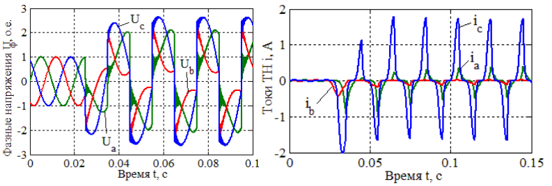
Image 5 – The calculated curves of phase voltages and currents in the VT winding with alternating ODZ. Sf = 1.5 uF
As noted above, the main factor determining the increase in current in the winding of a voltage transformer during an ODD is the effect of increased voltage. The resistor in the open-ended winding is not able to significantly affect the processes occurring in the primary winding of the VT during the ODZ, therefore, when over-excited, this method of protection against current overloads is ineffective. Such simple and obvious truths are insufficiently consecrated in the literature, so many experts have the false impression of the inefficiency of the ballast resistor. It turns out that the resistor is able to protect only from ferroresonance, and not from overexcitation. By introducing a similar classification of the causes of damage, it is possible to clearly and unequivocally recommend certain measures to protect TNCI against current overloads. And if a quenching resistor is sufficient to suppress ferroresonance, a slightly different approach is needed to combat overexcitation.
It cannot be argued that such a classification of the causes of VT damage was not known until now and is described for the first time in this article. The term ferroresonance
is well known and generally accepted. While the concept of overexcitation
is used less frequently and is classified by some authors as autoparametric ferroresonance [6]. From our point of view, it is unlawful to interpret transformer overexcitation as autoparametric ferroresonance. Hazardous currents in VT windings are not a factor in the existence of ferroresonance.
It is known that any resonant circuit is sensitive to active losses, therefore, with a certain value of the losses in the ferroresonance circuit, stable ferroresonance becomes impossible. At the same time, the authors of [6], in order to protect TNCIs from current overloads, propose connecting an additional resistor to the HV windings or VT neutrals with a value of 5–10 kOhm, which is several times greater than the intrinsic ohmic resistance of the HV winding. Calculations show that with an alternating resistor ODZ, such a value is enough to limit the current in the HV winding to safe values. However, it is obvious that the resistor does not contribute to any detuning of the resonance conditions, and its main task is that it acts as a voltage divider. With significant overvoltages and the transition of the VT from the magnetization inductance to the leakage inductance, the current in the HV winding is limited mainly by the active resistance of the additional resistor and the primary winding. The current limiting efficiency will be the higher the value of the additional resistance. It is impossible not to note the negative effect of the additional resistor on the metrological functions of the TNCI, which is proportional to the value of the additional resistor.
On the one hand, the solution to the problem of classification of VT damage is not able to solve the very problem of damage to measuring transformers. However, it is the existence of a clear and unambiguous classification of the causes of VT damage and an understanding of the true causes of damage that will allow us to find the most effective and universal solution. To suppress the FRF, it is effective to connect the quenching resistors to the open triangle winding. To combat the over-excitation of VT, it is necessary to provide measures to limit the overvoltage during DLD. The most effective way to limit overvoltages in the case of an ODD is resistive grounding of the network neutral [7]. In this case, the resistor is selected from the condition of equality of the active component of the current created by the resistor in the circuit, and the capacitive component of the current network. The limitation of overvoltages to 2–2.2 Uf will prevent the over-excitation of the VT and, accordingly, the occurrence of overcurrents and damage to the VT. In addition, the use of resistive grounding completely eliminates ferroresonance phenomena. This is due to the fact that the zero sequence circuit of the VT is shunted by a small resistance in the neutral of the network, therefore, the process of discharging the network capacitance through the windings of the transformer HV becomes impossible.
References
- Нагорный П. Д. Измерительные трансформаторы напряжения и контроль изоляции в сетях 6-35 кВ / П. Д. Нагорный, В. В. Назаров // Промышленная энергетика, 2002/№3, – С. 22–23
- Жураховский А. В. Режимы работы трансформаторов напряжения / А. В. Жураховский, А. Я. Яцейко, Р. Я. Масляк // Електроінформ, 2009/№1, – С. 8–11
- Виштибеев А. В. Повышение надежности электрических сетей установкой трансформаторов напряжения типа НАМИ / А. В. Виштибеев, К. П. Кадомская, В. А. Хныков // Электрические станции, 2002/№3. – С. 47–51
- Ганус А. И. Повреждаемость трансформаторов напряжения в областных электрических се¬тях АК
Харьковоблэнерго
и мероприятия по ее снижению / А. И. Ганус, К. А. Старков // Светотехника та електроенергетика, 2003/№1, – С. 76–82 - Зихерман М. Х. Исследование режимов работы трансформаторов напряжения контроля изоляции в сетях 6–10 кВ / М. Х. Зихерман, С. Г. Дунайцев, В. Г. Алексеев, Электрические станции, 1980/№1, – С. 56–59
- Дударев Л. Е. Исследование феррорезонансных процессов в сетях с изолированной нейтралью / Л. Е. Дударев, Эль-Хатиб Аднан, Электрические станции, 1993/№10, – С. 36–39
- Софинский А. В Резистивное заземление нейтрали в сети собственных нужд Энгельсской ТЭЦ-3 Саратовэнерго / А. В. Софинский, – Электрические станции, 2003/№2, – С. 34–36
- Лавров Ю. Л. Современные антирезонансные трансформаторы напряжения / Ю. А. Лавров, О. И. Лаптев // Новости электротехники, 2009/№5
- Саенко Ю. Л. Влияние характера горения дуги на повреждаемость трансформаторов напряжения контроля изоляции / Ю. Л. Саенко, А. С. Попов, 2011/№21. – С. 101–106