 DonNTU
 Masters' portal
Abstract
Contents
- Introduction
- 1. The relevance of the topic
- 2. The purpose and research tasks, planned results
- 3. The positioning system in the environment
- 4. The composition analysis equipment
- 5. Choice of programmable controller
- 6. Operational amplifier
- 7. Driver description
- 8. Description tracker
- 9. The principle of operation
- 10. Android settings-applications
- Conclusion
- References
Introduction
For robotic systems one of the most important tasks is to identify the situation (location) in the current time. This task is implemented by the development of specific control algorithms. Object management is carried out by using methods of artificial intelligence [1].
1. The relevance of the topic
Autonomous intelligent mobile robots are designed for automatic operation in in advance indefinite environment. They can be used in various fields of human activities and can solve various problems. For example, to deliver the goods, move various objects to produce intelligence, to produce any technology operation on a large area (e.g., cleaning), etc.
2. The purpose and objectives of the study
Aim – Development of model RC aircraft based on the STM32f407 microprocessor, the object must move along a predetermined path (line) that is determined by the sensor TCRT5000 (Line tracker sensor). Management should be accomplished via Bluetooth technology, using the mobile application.
Considering the incompleteness of the input information, and work in a dynamically changing environment, we formulate a number of tasks:
- to Develop the architecture of intelligent control systems;
- to Develop an algorithm for the identification and assessment of the environment;
- Develop, on the basis of these data the control system.
3. The positioning system in the environment
Initial task, and one of the most important for robotic systems is the problem of determining the current position, which is a robotic system.
To do this, the device is an intelligent mobile robot should include the software part. Before presenting the block diagram of the control system and situational identification, it is necessary to formulate a number of tasks that should be solved by the control system.
- Planning trajectories;
- Analysis of targets and split this task into several subtasks;
- Perform the movement generated by the trajectories, it is necessary to develop the nominal exposure for the actuators of the robot;
Figure 1 shows a diagram of the control system.
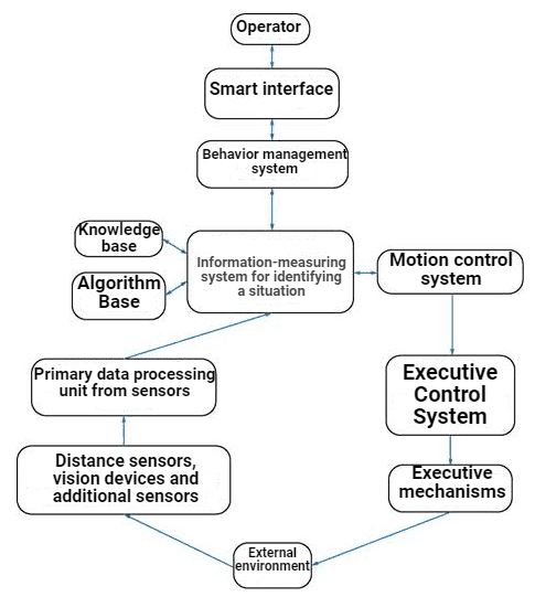
Figure 1 – The block diagram of the system control and identification
Primary unit of data processing takes the raw information from sensors about the state of the environment. In this unit, data is collected, sgruppirovany and processed. The output is formatted data transmitted via standard protocols. This is necessary for ease of connecting new sensors and clear systematization of data, which further facilitates working with data.
Information-measuring system of identifying a situation based on processed data builds a picture of the surrounding world. Data from the sensors is converted into a set of parameters, based on which other subsystems to make decisions.
Parameters are formed by using the knowledge base and algorithms. Here is the recognition of surrounding objects and build a sensory map of the environment. Our database contains algorithms mathematical algorithms to build on the basis of sensory data of the target card, recognition of environment and objects (recognition of sound images and pictures, digital signal processing), calculation of the necessary parameters and validate the obtained data. The knowledge base represents information about the external environment, laid at the stage of learning and is acquired in the process operation. Knowledge is organized and updated.
Control System behavior breaks the task into a sequence of subtasks and generates the robot's behavior to accomplish tasks. Creates a target point corresponding to the operation modes of the information-measuring system of identification. From it receives data on the implementation and displays them to the user. Also provides the user with processed information on the situation and sensory map received from the information – measurement system identification.
Traffic control System, considering the dynamic properties of the robot and the environment uncertainty generates a value of speed and direction for the implementation of the goals.
Intelligent interface is used to communicate with the operator. Its task is to monitor the robot and to monitor the achievement of the set goals.
Primary processing Unit performs processing and analysis of images coming from opto-electronic systems.
Given the nature of the tasks, consider the following restrictions and features:
- Information about the characteristics and background of the observed objects often contain inaccurate object size or absent;
- In light of limited time for decision-making and have a closed loop motion control processing, analysis and recognition must be performed in real time;
- Work management system, tracking and processing should be carried out with minimal human intervention or offline.
In difficult conditions, to improve the quality of the signal and the observation result by using algorithms for estimating the parameters of geometric transformations of images and methods of spatio-temporal filtering [2].
- For measuring position of moving and stationary objects observed for homogeneous and inhomogeneous background, used methods based on the comparison with the standard;
- Using information about the statistical properties of the object and the background can distinguish moving and stationary objects observed in a relatively homogeneous background. Such methods are called methods of statistical segmentation;
- When it detects objects in the background clear or cloudy sky maximum efficiency show methods of selecting objects using spatial filtering. These methods use the operation of linear and nonlinear spatial filtering of the images;
- Methods of selection of dynamic changes based on allocation changes over time in the observed group of images. Such methods are used in solving the problem of allocating moving objects.
Figure 2 shows the structure of the object detection system, which includes the above concept.
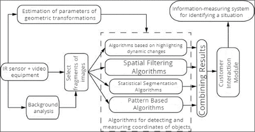
Figure 2 – Structure of program-algorithmic support of opto-electronic object detection system
4. Analysis of the composition of the equipment
As of the chassis used textolite plate and aluminum angles which are attached to motors with reduction gears, the gears attached to the wheels (figure 3).
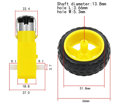
Figure 3 – Wheel and gear RC-car
System is controlled by microcontroller STM32f407 on debugging Board Discovery
.
To supply the object we use 3 series-connected batteries voltage 12 V.
Motor Control implemented through a DC-DC driver L298N. The motors are connected in series.
Trajectory is calculated using TCRT5000 sensors.
For the motion of an object uses 4 commutator motor. Two engines are installed the encoders l2523-60002. The value of output is for speed detection. Engines (figure 4), combined with the encoder 6 outputs [3]:
- 2 to the power of the engine;
- 2 channels of information;
- 2 for the encoder supply.
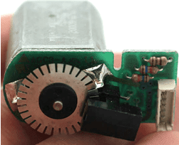
Figure 4 – Motor with encoder
As the encoder output signal has a sinusoidal form, OP is used to convert the signal into rectangular pulses (figure 6). The circuit uses opamps AD8544, which is soldered to the PCB SOPI14.
Connection Scheme shown in figure 5.
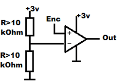
Figure 5 – connection Diagram encoder to OP
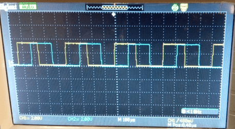
Figure 6 – Signals at the output of op-amp
5. Choice of programmable controller
STM32F407xx Family is based on high-performance ARM Cortex-M4 32-bit RISC core operating at a frequency of up to 168 MHz. The core has single precision floating point unit (FPU) which supports all of the user data processing ARM and the exact data types. Also implemented a full set of DSP instructions and a memory protection unit (MPU) which enhances application security.
STM32F407xx Family incorporates vysokoskorostniye built-in memory (flash memory up to 1 MB to 192 Kbytes of SRAM), up to 4 Kbytes of backup SRAM, and a wide range of advanced I / o and peripheral devices having 2 connections.
APB Bus, three bus AHB 32-bit matrix with multiple tire AHB [4]. All devices offer three 12-bit ADCS, two DACS, RTC, low power, twelve universal 16-bit timers including two PWM timers for motor control, two 32-bit General purpose timer.
Generator of true random numbers (RNG). They also feature standard and advanced communication interfaces.
- up To three I2C;
- Three SPI, two I2S in full duplex mode. To achieve precision audio class I2S peripherals can be synchronized via a dedicated internal audio PLL or via an external clock;
- Four USART and two UART;
- USB high speed OTG and USB OTG high speed with full speed (сULPI);
- Two CAN;
- Interface SDIO / MMC;
- Ethernet and the camera interface.
New advanced peripherals include an SDIO, an enhanced flexible static memory control (FSMC) interface (for devices offered in packages of 100 contacts or more), a camera interface for CMOS sensors.
Family STM32F407xx operate in temperatures ranging from -40 to +105 °C.
Range of power supply from 1.8 to 3.6 V. the supply Voltage can drop to 1.7 V when the device operates in the temperature range 0 to 70 °C with the use of an external power source.
Mode allows to design low-power applications.
STM32F407xx Family offers devices in various configurations from 64 to 176 pins. The set of included peripherals changes depending on the selected device.
These features make the STM32F407xx microcontroller family suitable for a wide range of applications:
- Motor drive and application control;
- Medical equipment;
- Industrial applications: PLC, inverters, circuit breakers;
- Printers and scanners;
- alarm Systems, video intercom, and HVAC;
- of home audio equipment.
Appearance of controller is shown in figure 7, a block diagram STM32F407 – the figure 8.
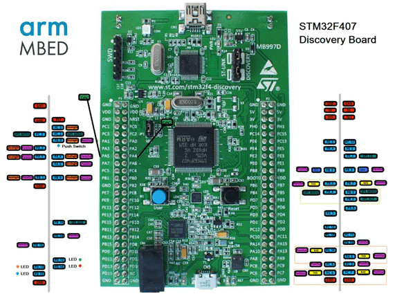
Figure 7 – Board STM32F407 Discovery
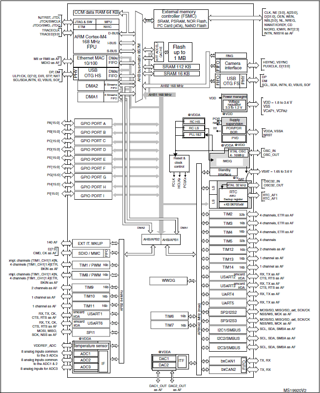
Figure 8 – the Block diagram STM32F407
6. Operational amplifier
Features of this series are in lower supply current with a bandwidth of 1 MHz, higher output current and better performance at a lower voltage.
AD8544 are single, dual and four channel amplifiers on the input and output with a single rail and very low supply current, bandwidth 1 MHz. It all works from a single power supply of 2.7 V, and from the power source 5 V. When powered 5 V in the circuit current is usually 60 the ICA, but even with 1 V bus power AD854x can provide an output current of 30 mA. These parts provide a bandwidth of 1 MHz low current consumption of 45 mA per amplifier.
AD854x series typically uses 45 a current µa per amplifier, which is much smaller than 200 mA to 700 mA, used in previous versions with similar characteristics. All these advantages make the AD854x series – a good choice for upgrading portable devices, as well as to increase battery life.
Better performance at lower voltages.
AD854x Family has been designed to ensure the best performance compared to previous versions when powered at 3.0 In 2.7 B.
Typical bandwidth gain close to 1 MHz with 2,7 V. voltage Gain with a 2.7 V & 3.0 V typically 500 000. The permissible supply temperature is over 60 °C, which greatly facilitates the use of this equipment.
Very low input bias currents include AD8544 for use in integrators, photodiode amplifiers, piezoelectric sensors, and other applications with high source resistance. Supply current is only 45 mA per amplifier, ideal for battery operation.
AD8544 are optimized to maintain high gains at lower supply voltages, making them useful for active filters and gain stages.
AD8544 is used for extended range industrial temperature (-40 °C to 125 °C). It comes in a narrow SOIC 14-lead TSSOP and 14 leads.
Block diagram of OPAMP is shown in figure 9.
Figure 9 – Block diagram of OP [5]
(animation: 6 frames, 7 cycles of repetition, 15.85 KB)
7. Driver description
L298 is an integrated monolithic circuit in 15-conclusions. This high-voltage double full pass driver with high current, designed for making standard TTL logic levels and drive inductive loads such as relays, solenoids, DC and stepper motors. Two enable inputs can enable or disable the device independently of input signals.
Emitters of the lower transistors of each bridge are connected to each other, and the corresponding external terminal can be used to connect an external sensing resistor. An additional supply input is provided so that the logic works at a lower voltage.
Technical features:
- Driver L298N;
- Medical equipment;
- Motor voltage up to 35 V;
- Logical voltage: 5 V;
- Size 44 x 44 x 30 mm.
Description text [6]:
- Vcc – the power of the engine;
- GND – land;
- OUT1, OUT2 – the output of the first channel;
- OUT3, OUT4 – the output of the second channel;
- ENA – turning on the first channel;
- IN1, IN2 – the direction of the first channel;
- ENB – turning on the second channel;
- IN3, IN4 – the direction of the second channel.
Appearance driver L298N is shown in figure 10, the block diagram – in figure 11.
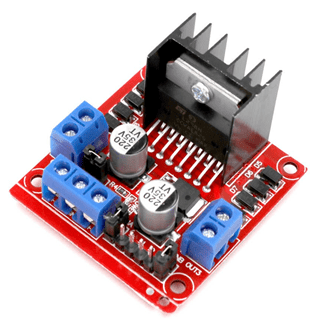
Figure 10 – Driver L298N
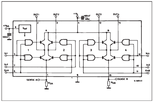
Figure 11 – Block diagram of the driver L298N
8. Tracker description
This IR reflective sensor uses TCRT5000 for determining color and distance. It emits the IR signal, and then detects whether it receives the echo. This sensor is often used in line following robots to automatically register data of the meter in the utilities, because this module can determine whether the surface is white or black.
Range of distance measurement from 1; mm to 8; of mm, and the Central point is about 2.5; mm. a built in potentiometer for sensitivity adjustment.
Infrared diode to emit infrared light continuously when the module is connected to the power source when the emitted infrared light is not reflected or its capacity is not large enough, the triode is in the off state, at this time, the D0 output logic LOW, and the signal indication led off.
Applications [7]:
- Detection of precipitation;
- fluid Leakage;
- Sensor on the overflow tank.
Features:
- supply Voltage: 3,3; In; ˜ 5; V;
- to Define distance: 1; mm-8; mm;
- Digital outputs HIGH when it detects objects;
- Led indicator on Board to show results;
- on-Board potentiometer to adjust the sensitivity;
- Built-in chip LM393.
The appearance of the sensor shown in figure 12.
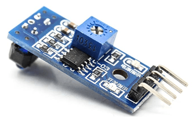
Figure 12 – Module digital sensor TCRT5000 line
9. The principle of operation
In the Android device are formed the operation of the machine, depending on the inclination of the smartphone/tablet, or from the pressed button. All the calculations are done in the Android application, and immediately calculates the PWM values for the left and right engines. The application has flexible settings, such as the range of the PWM, the sensitivity of the tilt, the minimum threshold PWM etc. Via Bluetooth transmits a command of the form:
- L – the command for left engine, R – for the right;
Minus
is the rotation of the motor for reversing;- 255 – number of PWM for Arduino this is the maximum speed of rotation;
- \r – end of the command.
L-255\r R-120\r
In this command, the machine will move back and slightly turn to the right, because the right engine will spin slower than the left.
L255\rR-255\r
In this command, the left motor will spin forward and the right back, forcing the machine to rotate around its axis counterclockwise.
H1\r
This command is used to enable optional channel to which you can connect the light source (led), a speaker, etc. as an example, given only one additional channel, however, easily be modified to use a larger number of additional channels.
Symbols L, R and H can be set in the Android settings application. Also to work with the memory of the microcontroller provides commands Fr – read values and the Fw – value.
For writing applications for Android can be used by Eclipse [8].
10. Android settings-applications
For each of the settings below has a little explanation, where they are responsible for what specific item (figure 13).
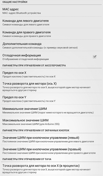
Figure 13 – A screenshot of the settings of an Android application CxemCar version 1.0 [9]
To establish communication with the Bluetooth module of the machine, in the application settings, you must specify the MAC address. You must configure the pair the devices in settings of your Android device. To do this, go to Settings Bluetooth and press the Search for devices
(figure 14), the phone finds our Bluetooth-module, click on it and enter the password.
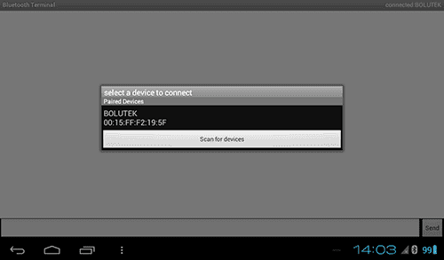
Figure 14 – Connecting the device [10]
Conclusion
During the development of the mobile robot on the basis of the objectives planned for implementation, was chosen as the microcontroller, and the necessary sensors to implement trajectory tracking and determining robot itself
in the space at the current time. In addition, during the execution of the project has been determined a control algorithm for a robot with a mobile device. All the signals to move the servos are generated from the pressed button, which gives a clear understanding of the device, which mode to operate [11].
In the future it is planned to bring all algorithms movement and orientation to automatism and the function implementation automatic Parking without human intervention, but only at the expense of the incoming signals from sensors and embedded algorithm.
This master's work is not completed yet. Final completion: June 2020. The full text of the work and materials on the topic can be obtained from the author or his head after this date.
References
- Simulink. [Электронный ресурс]. – Режим доступа: https://matlab.ru/products/Simulink
- WaijungBlockset. [Электронный ресурс]. – Режим доступа: http://waijung.aimagin.com/
- Reflective Optical Sensor with Transistor Output, DataSheet № TCRT5000
- DUAL FULL-BRIDGE DRIVER, Electronics Description, DataSheet № L298N
- Eclipse (среда разработки). [Электронный ресурс]. – Режим доступа: https://www.eclipse.org/
- Интерфейсная шина IIC (I2C). [Электронный ресурс]. – Режим доступа: http://easyelectronics.ru/...
- Управление мобильными роботами [Электронный ресурс]. – Режим доступа: https://moluch.ru/...
- STM32F407VE [Электронный ресурс]. – Режим доступа: https://www.st.com/...
- CMOS Rail-to-Rail General-Purpose Amplifiers, DataSheet № AD8541_8542_8544
- 1CxemCAR - Android-управление машинкой по Bluetooth. [Электронный ресурс]. – Режим доступа: https://cxem.net/...
- Датчик линии TCRT5000 цифровой. [Электронный ресурс]. – Режим доступа: http://know.smartelements.ru/...