 DonNTU
 Masters' portal
Abstract
Contents
- 1. Introdctin
- 2. Trolleybus simulation without ESS and with ESS
- 3. Comparison of the difference in energy consumption of trolleybuses without the proposed mass of ESS and with the proposed
- 4. Application in which the available energy is equal to the braking energy
- 5. Conclusion
- List of sources
1. Introdctin
When planning to equip the trolleybus with an energy storage system (ESS), the expected increase in weight should be taken into account, as the capacity is expected to be higher to provide more traffic. Knowing the structure of the DC network and cable parameters, virtual simulations can be very useful in obtaining graphical data for different drive cycles. The description of the Matlab/Simulink simulator model for the trolleybus traction drive and other calculations of mechanical parameters have been discussed in [1]. During the simulation of the trolleybus movement, the transmission resistance values are set according to the trolleybus location, i.e. the distance travelled from the supply substation. The study of stationary supercapacitor (SC) sets is considered in [2] and [3]. The main objective of this work was to investigate the prospective efficiency of mobile SC ESS supercapacitors for the Skoda 27Tr trolleybus. A number of simulations of trolleybus with equal driving conditions were performed, except for the initial distances from the substation. Several applications of the ESS SC connection were tested, ranging from a minimum of 4 to a maximum of 16 SC module numbers. The impact of the extra mass of ESS on the trolleybus energy is analyzed and compared with the regenerative braking energy. In addition to the higher energy consumption, the transmission losses are theoretically expected to be higher in the following cases. However, thanks to the ESS, which facilitates the energy supply of the trolleybus drive in acceleration mode, transmission losses can be significantly reduced. Although the power of the trolleybus in acceleration mode increases, the braking power also increases slightly and a higher amount of braking power is expected. Finally, recommendations are made on how to select the ESS SC module number based on the simulation results.
2. Trolleybus simulation without ESS and with ESS
Figure 1 shows the model of the trolleybus Skoda 27Tr Solaris and the ESS SC Maxwell BMOD0063 module with m=60 kg. C=63F R=0.018Ohm and U, =125V. Mechanical and electrical parameters of the considered trolleybus: gear ratio 6.2, weight 16500kg, seats 50+1, maximum number of passengers 160, wheel diameter 0,9565m, rated power 260kW. Although passenger mounting and vehicle weight shall be measured in real time in real situations [4]. [5], for further simulations of the trolleybus operation it is assumed that there is 1 driver and 80 passengers inside the trolleybus. Suppose that the average person weight is 75 kg and the trolleybus weight is 22575 kg, which has a corresponding moment of inertia, the calculation principle of which is described in [1]. Each simulation lasted 65c and was performed at a distance of 665m [1]. While investigating the trolleybus movement at a certain mass, three simulations were carried out with the same control torque schedule. Thus, each time the trolleybus traveled the same distance, which was added to the initial distance for each simulator. Further results will show how as the distance between the trolleybus and the substation increases the corresponding losses and voltage drops in the air network. Firstly, a simulation series of trolleybuses without ESS was carried out. Then, a simulation series of trolleybuses without ESS was carried out, but with a larger mass due to the proposed ESS implementation options. Finally, trolleybus simulations with ESS were carried out. Fig. 2 shows the simulated SC connection configurations with 4 to 16 modules, the percentage increase in trolleybus mass and the maximum kinetic energy values.
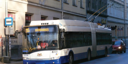
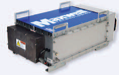
Figure 1. – Skoda 27Tr Solaris trolleybus and SC BMOD0063 module.
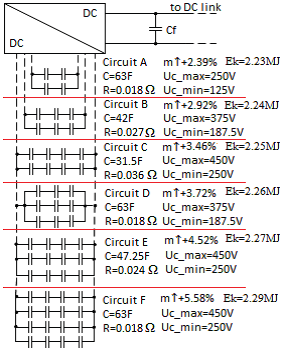
Figure 2. – SC ESS Connectivity Options
In addition to the SC modules, the ESS also includes a powerful DC/DC converter weighing at least 30 kg. The minimum voltage of the ESS must be half the rated voltage of the ESS to operate the inverter accurately and to simplify the design [6]. The maximum ESS voltage is set to 450 V instead of the rated 500 V in C, E and F circuits, since the ESS voltage must not be higher than the air supply voltage, which can be significantly reduced by transmission losses. Both the short 12 m 2-axle trolleybus model Skoda 24Tr and the long 18 m 3-axle model Skoda 27Tr have an internal backup room. If a diesel generator is not installed, it is possible to use ESS, not only on the roof.
3. Comparison of the difference in power consumption between trolleybuses without the ESS masses offered and those offered.
Due to the increase in trolleybus weight caused by the ESS schematics from Fig. 2, the torque reference graph was modified for each case to obtain the same speed and distance graphs as in Fig. 2. 3. and the figure. 4 shows how, when the mass of the trolleybus increases, the energy of the trolleybus drive is increased by additional ESS modules in equal driving conditions. In addition, the graphs showing the difference in percentage of the energy of the drive are brief. When a trolleybus with a higher mass reaches a certain speed, more energy and more power are consumed. In braking mode, therefore, slightly more energy is recovered and in the figure. 4 also shows the difference in braking energy. From each 665 m interval, the drive and braking energy was measured from scratch.
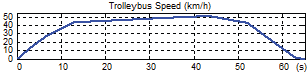
Figure 3. – The trolleybus speed diagram
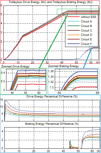
Figure 4. – Charts of trolleybus energy and braking energy consumption
In Fig. Fig. 4 shows how the additional mass of ESS in the case of circuit A with Fig. 2 increases the energy consumption of the trolleybus drive by 2.7 percent. With each successive proposed ESS, this energy continues to increase up to 6.26 per cent for Chain F. The higher the mass of the trolleybus, the more power is needed to drive. This increases the braking energy of the trolleybus by 2+4.4 %. If the trolleybus has an ESS, to which the braking energy is transferred, the braking energy is subtracted from the trolleybus energy diagram. From the end of the diagram it can be calculated that during the simulations the trolleybus braking energy, which can be stored in the ESS, fills 25 ± 1 % of the trolleybus drive energy that is consumed during acceleration. If we look at the amount of energy that can be recovered by the ESS, the increase in the energy consumption of the trolleybus driver caused by the additional mass of the ESS can be considered negligible. Further, how the additional mass of the trolleybus ESS affects the amount of energy lost during transmission over the DC air network will be investigated.
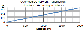
Figure 5. – DC network transmission resistance diagram
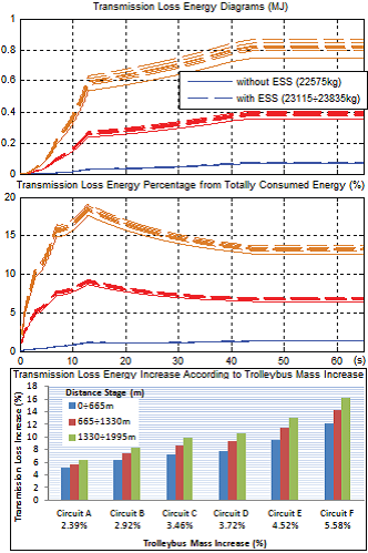
Figure 6. – Transmission energy loss diagrams and percentage difference(comparison)
In Fig. 6 also shows how many percent of the total energy consumed, i.e. the transmission loss energy plus the trolleybus drive energy, contains transmission loss energy. The bar graph shows the percentage by which the amount of transmission loss increases when the trolleybus mass exceeds 22575 kg. For trolleybuses with a higher mass starting from 23115+23835 kg, the transmission loss increases quite noticeably by 5+16%. However, the percentage of energy losses during transmission from fully consumed energy increases only by 0.03+0.07% at 0+665 m, at 665+1330 m - 0.18+0.46%, at 1330+1995 m - 0.41+1.05%.
4. An application in which the available energy is equal to braking energy
When planning a future-oriented ESS for electric transport, the maximum speed at which it must brake must be taken into account. As can be seen in the figure. 4, at 50 km/h without ESS in braking mode, 1.311 MJ is generated. However, it should not be considered as the maximum amount of energy that ESS can store, charging from minimum to maximum voltage. The trolleybus equipped with ESS is heavier and the amount of recovered energy will also be slightly higher. From a simulation with the extra mass of ESS in the A circuit body, the braking energy is 1.328MJ, which is 1.3% higher. Since the amount of braking energy is predicted based on these simulations, it can be compared with the estimated mass available for ESS SC:
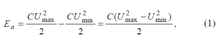
where C is the capacitance of the supercapacitor (F), Umax is the maximum voltage (V) and Umin is the minimum voltage (V) of ESS, equal to half the normal, not the maximum, voltage of ESS.
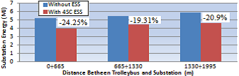
Figure 7. – Substation power consumption diagrams without and with ESS for different distances
Part of the energy is lost due to the active resistance of the ESS SC connection shown in Figure 2. Fig. 10 shows different graphs of energy obtained by simulating the trolleybus movement at a distance of 655+1330m. During acceleration, the ESS and the corresponding SC energy are presented as negative discharges. It continues to decrease until the minimum ESS voltage is reached. In braking mode, the ESS is charged and the corresponding SC energy is increased. The previously mentioned braking energy of 1.328MJ was transferred to ESS. However, in Figure 10, the measured SC energy in the ESS is 1.24 MJ, since the remaining energy of 0.084 MJ was lost due to an active resistance of 0.018 Ohm. The graph of the lost SC energy in ESS mode is shown to increase in motor mode, since the voltage drop of the ESS is negative and the SC current flowing from the ESS is negative. By multiplying them, we obtain positive power. When the ESS SC is charged, the SC current is positive and the voltage drop from the SC voltage is also positive. Consequently, the amount of energy in the active resistance of the ESS SC continues to rise above zero. In the end, 6.31% of the braking energy is lost during the accumulation process and about 5.9% of the ESS energy does not reach the trolleybus motor in acceleration mode, i.e. it is lost when the ESS supplies the trolleybus with energy, and this is compensated by getting more power from the substation, and this fact has contributed to the substation energy consumption diagram shown in Figure 9.
5. Заключение
With an increase in the mass of the trolleybus by 2.39+5.58% due to a certain ESS, the trolleybus drive energy increases by 2.7+6.26%. The regenerative braking energy increases by 2 + 4 % and contains approximately 25 % of the energy consumed by the trolleybus drive. Depending on the location of the trolleybus, the transmission loss energy increases by 5 + 16%. Therefore the total energy consumption of the trolleybus increases by only 1.05%. Thanks to the ESS system, which provides the trolleybus traction power supply in accelerated mode, so that less energy is taken from the substation by about 50%, the amount of transmission losses is reduced by about 50%. A fully-charged SC ESS system with a higher maximum voltage and higher capacity can take longer to power the trolleybus drive and can operate in stand-alone mode. If this is not required, a minimum of 4 SC ESS was considered the optimal application for Skoda 27Tr, as the available ESS energy was almost equal to the braking energy of the trolleybus at maximum speed. Furthermore, it was suitable even for a complete trolleybus that generates higher braking energy than the available ESS energy. Due to the active resistance of the ESS a rather significant amount of energy is lost, which is approx. 6+7% during both power supply and braking. To reduce the active resistance of ESS, parallel connection of other SC modules is being considered. In general, with the 4 SC ESS, the total substation energy consumption, including both transmission energy loss and traction energy supply, has been reduced by 19.31+24.25 %, depending on the location of the trolleybus in the 2 km distance of the substation.
List of sources
G. Stana, V. Brazis, "Trolleybus Motion Simulation by Dealing with Overhead DC Network Transmission Losses"
U. Sirmelis, J. Zakis, L. Grigans, "Optimal Supercapacitor Energy Storage System Sizing for Traction Substations"
D. Iannuzzi, P. Pighetti, P. Tricoli, "A study on Stationary Supercapacitor sets for Voltage Droops Compensation of Streetcar Feeder Lines"
K. Kondratjevs, N. Kunicina, A. Patlins, A. Zabasta, A. Galkina, "Vehicle Weight Detection Sensor Development for Data Collecting in Sustainable City Transport System"
A. Patlins, N. Kunicina, "Real-Time Collection and Easy Passenger Counting Method for Public Transport System"
H. Xia, H. Chen, Z. Wang, F. Lin, B. Wang, "Optimal Energy Management, Location and Size for Stationary Energy Storage System in a Metro Line Based on Genetic Algorithm"
U. Sirmelis, "Direct Connection of SC Battery to Traction Substation"