
Abstract
Contents
- Introduction
- 1. Theme urgency
- 2. Goal and tasks of the research
- 3. Analysis of the TVG–8M hot water boiler as an automation object
- 3.1 Formalization of the control object
- 4. Development of a structural diagram of ACS
- 5. Development of mathematical models of the basic elements of ACS
- Conclusion
- References
Introduction
The technological processes occurring in the boiler unit during its operation are characterized by a number of interrelated parameters. A change in one of them should be reflected in all other parameters: steam pressure, amount of air supplied, amount of fuel supplied to the furnace and exhaust flue gases, feed water flow rate.
Automation of boiler houses provides for the automatic regulation of the production process, automatic heat engineering control, remote control and signaling of deviations from the normal operating mode. Automation of boiler plants can be partial, in which the automation of certain types of equipment is carried out, or complex, in which the boiler plant is operated without permanent staff.
During operation of boilers equipped with relay–contact automation, emergency conditions often occur. To determine the pre–emergency modes, a certain level of qualification of the operating personnel is required, and timely regulation of the process of heat energy production requires constant monitoring of the process parameters by the operator. Of course, the industry now produces a wide range of hot water and steam boilers. But, unfortunately, most of the automation systems supplied with the boiler plants are still implemented on the basis of relay–contact elements. In addition, a large number of boiler plants, operated in almost all boiler rooms, still have a sufficient supply of resources, their complete replacement is not justified.
The main task of automation of a boiler installation is to regulate: the air and fuel supply depending on the load of the boilers, provided that the steam pressure in steam boilers or the temperature of the water boilers is kept constant.
Automatic control of air and fuel supply depending on the load of the boiler, water temperature within specified limits and regulation of draft (vacuum in the furnace) is called automation of the combustion process.
1. Theme urgency
The master's work is devoted to the urgent task of developing a system for the automatic control of a boiler room. Which will help:
- reduce operating costs for the process of thermal energy
- production in the conditions of a district boiler house;
- increase the efficiency of facility management;
- increase savings in resources (gas);
- increase the annual economic effect.
2. Goal and tasks of the research
The purpose of the development is to increase the efficiency of the process of heating water in boilers by developing an automatic control system that will help maintain a constant temperature of the water leaving the boiler, as well as reduce operating costs for the process of heating it.
To achieve this goal, you need to solve the following tasks:
- Perform an analysis of the functioning of the TVG–8M boile
- To develop a structural diagram of ACS.
- Perform synthesis of ACS.
- Check system performance.
3. Analysis of the TVG–8M hot water boiler as an automation object
The boiler room of the district heating system of the city microdistrict is designed for heating industrial and residential buildings, as well as social and cultural facilities. Most often, such boiler houses are sold on the basis of hot water boilers that run on natural gas.
The boiler room is designed to heat the working fluid (water) for a heating system or steam supply, is located in the same technical room, and is used for district heating of buildings. The considered district boiler house is equipped with TVG–8M hot water boilers (Fig. 1)
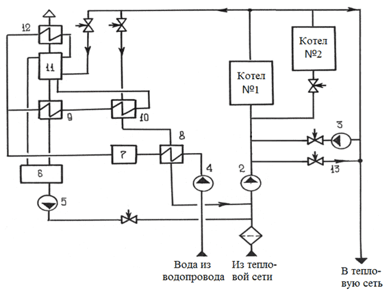
Figure 1 – Technological scheme of the boiler
In fig. 1 marked: 2 – network pump; 3 – recirculation pump; 4 – feed pump; 6 – a tank of make–up water; 7 – water treatment plant; 8 – raw water heater; 9, 10 – heat–treated water heaters; 11 – deferator; 12 – evaporation cooler; 13 – line bypass.
A hot water boiler is a device designed to produce hot water due to the heat generated by burning fuel. The TVG–8M gas–fired water–tube gas–fired boiler is a direct–flow sectional heat generator with forced water circulation, equipped with a separate smoke exhauster and fan. The generalized technological scheme of a gas–fired gas boiler is shown in Fig. 2.
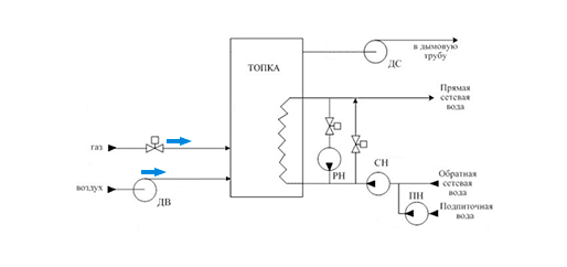
Figure 2 – Technological scheme of the boiler
Animation: 7 frames, 0.5 sec delay, size 16.9 KB, 10 repetitions, program – Easy GIF Animator 6
The TVG–8M boiler is equipped with hearth diffusion burners (4 pcs.), The air to which is supplied by a DV blow fan (without forced air supply to the burners, the boilers satisfactorily operate at loads up to 40% of the nominal.). The burners are installed in the boiler compartments between the double–light screens, each of the burners has two rows of holes, with a diameter of 1.5 mm, arranged in a checkerboard pattern. The combustible mixture that forms in the burner ignites and transfers heat to the combustion chamber. As a result of the combustion process, gaseous products are formed – flue gases. They enter the convective gas duct through an opening 800 mm high above the dividing wall, and then the DS exhaust fan emits them into the atmosphere. The temperature of the exhaust gases behind the boiler is 190–210 °C.
When burning gas fuel, it is necessary to ensure: good preliminary mixing of the gas with air, the process with small excess air, separation of the mixture flow into separate jets. The heating of the gas–air mixture and the chemical reaction of combustion proceed very quickly. The main factor in the burning time is the time taken to mix the gas with the air in the burner. The speed and completeness of gas combustion, the length of the furnace flame and the flame temperature depend on the speed and quality of mixing gas with the required amount of air. For the combustion process of the smoke exhauster, the necessary vacuum is created and the complete removal of combustion products is ensured. If you achieve the ratio of air flow in accordance with the fuel supply, the combustion process will be carried out with maximum efficiency.
To reduce the intensity of external corrosion of pipes of boilers, it is necessary to maintain the temperature of the water at the inlet to the boilers above the temperature of the dew point of the flue gases. The minimum permissible water temperature at the inlet to the boilers when operating on natural gas is 70 ° C. To ensure this, it is necessary to supply a certain amount of hot water leaving the boilers, again to the entrance to the boiler for mixing with water from the return pipe and make–up water. The line along which heated water is pumped from the boiler exit to its entrance, as well as a special pH pump, is called recirculation (Fig. 2).
The presence of recirculation and water bypass lines leads to specific modes of operation of boilers. Water boilers operate reliably only if they maintain a constant amount of water passing through them. On the other hand, with high–quality regulation of heat consumption in a stationary mode, a constant flow rate of the coolant in the heating network is required, a constant pressure difference in the direct and return pipelines of the consumer for the implementation of the design hydraulic settings for heat consumption. Manual adjustment by operators of the aforementioned control loops using conventional valves without automation means, controllers do not lead to economically viable results.
As a rule, 2 boilers operate in the boiler room at the same time, therefore it is advisable to use cascade–related regulation with the main controller. He perceives a change in the temperature of the outside air and the temperature of the direct water, i.e. in the common collector. The main regulator acts on the fuel regulators of all boilers. In addition, a signal is supplied to the fuel regulator from the water temperature sensor at the outlet of the boiler and from the return water temperature sensor. Thus, the fuel supply varies depending on the outdoor temperature, the temperature in the common collector, the temperature of the water behind the boiler and the temperature of the return water.
Air must be supplied in such a quantity as to ensure complete combustion of the fuel. If there is not enough air, then in addition to incomplete combustion, there will also be air pollution. If there is an excess of air, there will be an entrainment of heat into the pipe. Thus, it is necessary to adjust the fuel–air
ratio.
Fuel can go of different quality, and the calculated ratio ratio may not be optimal. To improve the quality, it is necessary to control the completeness of fuel combustion by the oxygen content in flue gases. Thus, the air regulator will change the air supply depending on the fuel consumption, air consumption, with correction for the oxygen content in the flue gases.
For the combustion process in the furnace, a vacuum must be created, if it is insufficient, then the flame can be extinguished. If too large, then the flame breaks off the burner. The vacuum is regulated depending on the air flow, by changing the performance of the smoke exhaust.
3.1 Formalization of the control object
The above analysis of the characteristics of the boiler allows you to get a diagram of the main control channels and the relationship of technological parameters (Figure 3).
The control quantities are:
- gas consumption Fâ(ě³/÷);
- đŕńőîä âîçäóőŕ Fă(ě³/÷);
- water temperature °Ń.
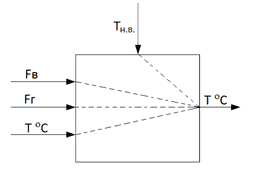
Figure 3 – Representation of a boiler as a control object
4. Development of a structural diagram of ACS
Based on the previously performed analysis of the features of the boiler used as an automation object, and also taking into account the concept of ACS construction, a block diagram of the automatic control system of the boiler is developed (Fig. 4).
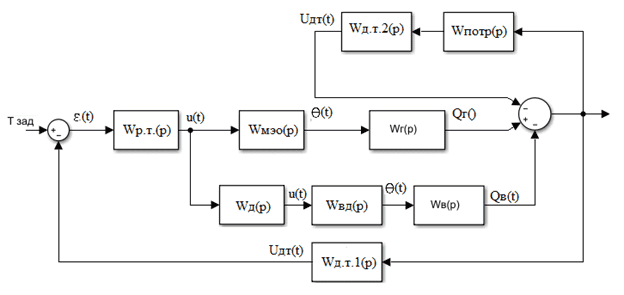
Figure 4 – Structural diagram of ACS
The control object of the ACS is a hot water boiler, its output parameter is the temperature of the water leaving the boiler, which varies depending on changes in the temperature of the outside air, the temperature of the return network water and the flow rate of the supplied gas. The quantity (flow rate) of air supplied to the boiler furnace determines the efficiency of the combustion process and is associated with the flow rate of the supplied gas through the gas–air
ratio – Kń. Disturbing effects are a change in the outdoor temperature and the temperature of the return network water.
5. Development of mathematical models of the basic elements of ACS
According to the structural diagram of ACS (Fig. 5) we obtain a model of elements of ACS. From here you can get a structural diagram of a model of a hot water boiler, which is shown in Figure 5.
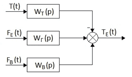
Figure 5 – Structural diagram of a model of a boiler
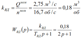
Figure 5 shows that the control object is a hot water boiler, the output value of which is the water temperature at the boiler outlet ŇE (t), and the input values ??are the gas flow rate FE(t), air flow rate FB(t) and the return temperature Ň(t).
Experimentally determined the change in gas flow and temperature of the network water at the outlet of the TVG–8M boiler.
The real values ??of k, T, and τ are found from experimental data or structural calculations.
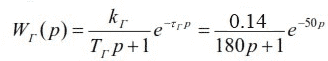
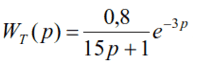
The transfer function along the channel for changing the temperature of the network water at the outlet of the boiler will be:
where 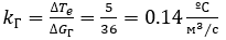 is the transfer function of the object without delay.
and the transition process time of 180 seconds, substituting the coefficients, we get:
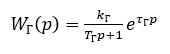
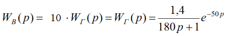
When burning fuel into the combustion chamber, there must be a certain amount of air in our case KC=10. That is, in order for the combustion process to be as economical as possible, it is necessary to supply 1 part of fuel and 10 parts of air. Then the transfer functions WB(p) and WT(p) will be of the form:
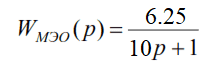
As an actuator that changes the flow rate of gas supplied to the boiler, there is an electric single–turn mechanism (MEO) that controls the disk shutter. The nominal full stroke time is 30 seconds. It can be described by the following transfer function:
As an actuator that changes the amount (flow rate) of air supplied to the boiler, there is a centrifugal blower fan VDN–11.2, which is described by the following transfer function:
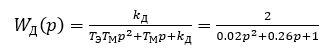
where TM is the electromagnetic time constant of the electric motor, s;
TÝĚ – mechanical time constant of the electric motor, s;
kÄ – gear ratio of the electric motor.
The dynamic properties of the VDN–11.2 blower fan can be described with a sufficient degree of accuracy by the first–order inertial link with the following transfer function, where TÂÄ is the time constant of the blower fan, TÂÄ=2s and the gear ratio of the blower fan kÂÄ is:
whereĺ TT = 15–20 – thermocouple time constant, s;
mT is the nominal static conversion coefficient (slope of the characteristic) of the thermocouple,
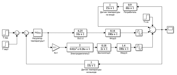
Figure 6 – Block diagram of the simulation of ACS
As a typical controller, select the PID controller. Since it is universal. Using this regulator, you can get any law of regulation, since it includes all the components of other laws. Another advantage of the PID controller is its ability to anticipate the expected deviation of the controlled variable, responding only to the existing deviation. It produces an additional regulatory action proportional to the rate of deviation of the controlled variable from the set value.
To configure the regulator parameters, the capabilities of the Simulink package are used. When you click on the Tune
button in the parameters window of the PID Controller
block, the selected controller is automatically tuned.
As a result of automatic tuning, the following values of the temperature controller parameters were obtained: kĎ=2.762; kČ=0.01; kÄ=-46.463.
To assess the quality of control in ACS with the developed PID control law, the process of changing the temperature of the water at the outlet of the boiler with a disturbing change of 20 °Ń (at time t=1500 c) and a change in the target action of 20 °Ń (at time t=2000 c)
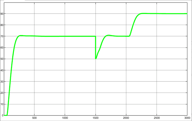
Figure 7 – Change in water temperature at the boiler outlet using the developed ACS
Conclusion
The theoretical synthesis of the temperature controller at the outlet of the boiler was carried out in the work.
The performed modeling using this model showed a satisfactory quality of controlling the temperature of the water at the outlet of the boiler, both through the channel of the setting action and the channel of the disturbing effect.
References
- Ŕőěĺňćŕíîâ Đ.Ä., ńňóä.; Ôĺäţí Đ.Â., äîö., ę.ň.í., Îńîáĺííîńňč ŕâňîěŕňč÷ĺńęîăî óďđŕâëĺíč˙ âîäîăđĺéíűě ęîňëîě ńčńňĺěű öĺíňđŕëčçîâŕííîăî ňĺďëîńíŕáćĺíč˙ ăîđîäńęîăî ěčęđîđŕéîíŕ / (ĂÎÓÂĎÎ
Äîíĺöęčé íŕöčîíŕëüíűé ňĺőíč÷ĺńęčé óíčâĺđńčňĺň
, ă. Äîíĺöę, ÄÍĐ) - Áóçíčęîâ Ĺ.Ô., Đîääŕňčń Ę.Ô. Ďđîčçâîäńňâĺííűĺ č îňîďčňĺëüíűĺ ęîňĺëüíűĺ. – 2–ĺ čçä., ďĺđĺđŕá. – Ě.: Ýíĺđăîŕňîěčçäŕň, 1984. – 248 ń, čë.
- Ëčďŕňíčęîâ Ă.Ŕ., Ăóçĺĺâ Ě.Ń. Ŕâňîěŕňč÷ĺńęîĺ đĺăóëčđîâŕíčĺ îáúĺęňîâ ňĺďëîýíĺđăĺňčęč. Ó÷ĺáíîĺ ďîńîáčĺ. Âëŕäčâîńňîę, Äŕëüíĺâîńňî÷íűé ăîńóäŕđńňâĺííűé ňĺőíč÷ĺńęčé óíčâĺđńčňĺň, 2007ă. – 137ń
- Ëčďîâ Ţ. Ě. Ęîňĺëüíűĺ óńňŕíîâęč č ďŕđîăĺíĺđŕňîđű/Ţ.Ě. Ëčďîâ, Ţ. Ě. Ňđĺňü˙ęîâ. – Ěîńęâŕ–Čćĺâńę: ÍČÖ
Đĺăóë˙đíŕ˙ č őŕîňč÷ĺńęŕ˙ äčíŕěčęŕ
, 2003. – 592 ń. - ĎŔÎ
Ěîíŕńňűđčůĺíńęčé ÎŇĘÇ ěŕřçŕâîä
Îďčńŕíčĺ âîäîăđĺéíűő ęîňëîâ ŇÂĂ - Đűáŕëĺâ Ŕ.Í. Ŕâňîěŕňč÷ĺńęîĺ óďđŕâëĺíčĺ ýíĺđăĺňč÷ĺńęčěč óńňŕíîâęŕěč. Ó÷ĺáíîĺ ďîńîáčĺ. Áëŕăîâĺůĺíńę. Ŕěóđńęčé ăîńóäŕđńňâĺííűé óíčâĺđńčňĺň, 2007ă. – 105 ń.
- Ôŕéĺđřňĺéí Ë.Ě., Ýňčíăĺí Ë. Ń, Ăîőáîéě Ă.Ă. Ńďđŕâî÷íčę ďî ŕâňîěŕňčçŕöčč ęîňĺëüíűő. Ě.: Ýíĺđăč˙, 1978. – 344 ń.