Abstract
Contents
- Introduction
- 1. Brief information about the main parameters of antennas
- 2. Fresnel zone antenna. Operating principle
- 3. Design section
- 4. Conclusions
- List of sources
Introduction
Antennas are one of the most important parts of modern spacecraft.
He history of the formation of space antennas is closely related to the history of development of rocket and space technology, including the very first antennas of various design designs are used in communication systems, remote sensing and natural monitoring.
Collapsible space antenna – antenna, where the passage through the atmosphere of the spacecraft is assembled and does not take up much space, and when you get into space at the command of the software–time device is disclosed and converted to the desired state for optimal performance, direction and scale.
The relevance of reducing the weight and size characteristics is very high, this is due to the fact that the cost of transportation and putting the antenna into orbit is significantly reduced, and their characteristics remain the same.
The very first antennas were of rigid construction because of what, they had a small diameter, allowing to place the structure under the fairing of the spacecraft. At the same time, the increase in operating frequency ranges caused the need to increase the aperture diameter of space antennas. Consequently, antennas of rigid construction due to size limitations under the fairing are not applicable for the entire frequency range. Transformable space antennas do not have this flaw and in the unfolded state can be sufficiently large aperture diameter.
Prior to attachment to the spacecraft, the antennas are installed in a folded state.
To transformable devices impose, first of all, the conditions for rigidity, because of the need for orientation of the antenna and the accuracy of the working surface of the reflector.
Antennas are also required to have as little mass and size as possible when assembled, they must have a robust deployment system, and they must maintain their performance when operating [1].
During the improvement of antennas, they became more complicated, which is why there were fundamentally new classes of them, expanded their functions. As a rule, antennas from simple devices turned into complex dynamic systems, containing in most cases hundreds, thousands of different elements.
Consequently, the designs of large space reflectors are based on the principles of changing the geometry of the object, for example, such as mechanical deployment or extension of rods, filling with air compactly folded structures and stretching the membrane between the structural elements.
1. Brief information about the main parameters of antennas
The main characteristics and parameters of the receiving and transmitting antennas are [2]:
– bandwidth;
– polarization;
– input impedance;
– standing wave ratio;
– polar pattern;
– directional factor;
– antenna gain;
– antenna efficiency;
– antenna noise temperature.
2. Fresnel zone antenna. The principle of operation
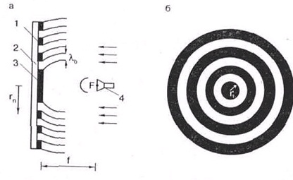
Fresnel Zone antenna (ZAF) – a surface on which only some selected zones are made reflective of radio waves. The shape and size of these zones are chosen so that the reflected waves are formed at one point. It consists of many flat concentric rings arranged in the same plane [3].
In figure 1 a, ZAF is shown on the side, in the section, where: 1 – metal rings, 2 – dielectric base, 3 – central disk, 4 – converter.
Figure 1 b shows ZAF, front view.

Figure 1 – Schematic representation of ZAF
The main advantage of ZAF – simplicity of manufacturing technology, as it is flat. Such an antenna can be made of a large piece of foil plastic either by etching or by cutting out the gaps between the rings. It is also possible to make a sticker of rings from a foil or equal tin on a sheet of a getinax, a textolite, Plexiglas, a wood-fibrous cloth. To reduce the wind load in the dielectric base of the antenna can be drilled any number of holes.
The main disadvantage of ZAF is a smaller CU compared to a parabolic antenna of identical diameter, since not all signal energy incident on the antenna web is directed to the irradiator. Under weak signal conditions, a gain loss of even 2 dB can result in signal noise and color loss. To compensate for the lack of KU ZAF it is necessary to increase the diameter of the antenna web, although with sufficient power of the satellite repeater and at large angles for a given reception point, this antenna can provide good results.
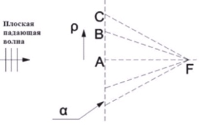
The work of ZAF is shown in figure 2. A plane wave propagates in free space. The Huygens principle says that EMF at point F can be described as a superposition of an infinite number of point emitters of spherical waves on plane A. For example, at point F there is a contribution from the source at point A. for any other point on the plane, the distance to F will be greater than the distance AF, which means that the phase from the contributions of these points is different. The contribution phase from point B, for example, is shifted by some amount from the contribution from point A. The distance between A and B can be chosen in such a way that at a given frequency the phases of the contributions from the two points will differ by K radians. Then the contributions to the field at point F from A and B will be in antiphase and interfere with weakening. Similarly, point C can be chosen so that the contributions from A and C are in phase and add up. Each of these points marks the two–half–period Fresnel zone. This means that in figure 4, each point between A and C is in the same two–half–period zone. Of course, the geometric location of the points that mark the boundaries of each two–half–period zone is a circle on the plane a.

Figure 2 – Illustration of Fresnel zone concept
Each point on plane a has a corresponding point within the same two half period zone whose contribution is exactly opposite in phase. Also, each point between A and B has a corresponding opposite–phase point between B and C. Jacques–Louis Soret said that if the opposite–phase contributions can be removed, the remaining contributions will be added to the point F with mutual reinforcement. By making the alternating areas of each zone on the plane transparent and opaque to electromagnetic radiation, the zone plate can be constructed so that it will have the focusing properties of the lens. Therefore, there are two half–period zones on each half–period zone [4]
3. Design section
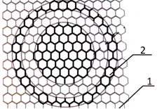
The design of the folding antenna consists of a set of honeycombs and is shown in figure 3.

Figure 3 – Folding antenna design
Where: 1 – radiopransparent material 2 – metallized material.
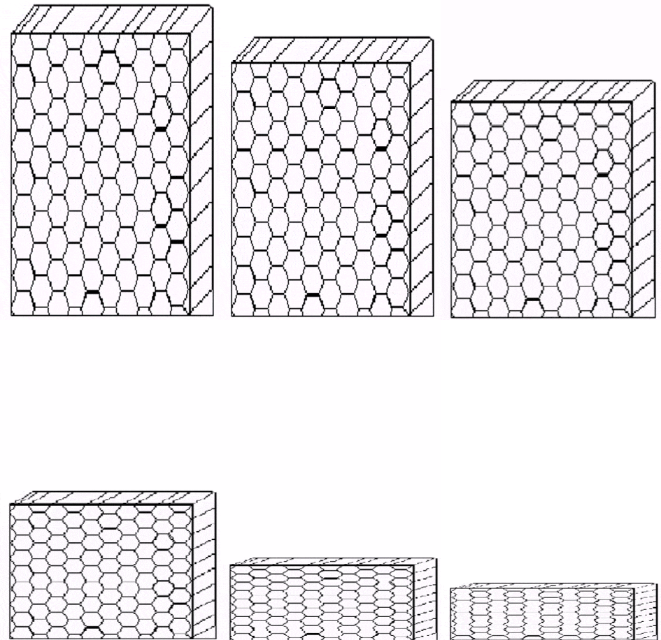
The method of adding and unfolding ZAF is shown in figure 4 (animation).

Figure 4 – Method of addition and opening ZAF
(animation: 6 frames, 144 kilobytes, 6 cycles)
The principle of the zonal aperture of the Fresnel antenna, shown in figure 4, is that at the exit of the satellite into orbit on command from the timer counter triggers a spring, which is mounted on the opposite side of the antenna, when triggered, the spring, she straightened
due to what is happening and revealing of the antenna.
Conclusions
In the course of the final work, an option was proposed and considered to reduce the weight and size characteristics of the Fresnel zone antenna, through the use of specialized materials and design changes, which can significantly reduce the cost of transporting and launching the antenna into orbit.
Source List
Лопатин, А. В. Обзор конструкций современных космических антенн / А. В. Лопатин. – М.: Наука и техника, 2007.– 56 с.
Параметры антенн [Электронный ресурс]. – Режим доступа: http://antenna.nnov.ru
Драбкин, А. Л. Антенно-фидерные устройства, учебник для ВУЗов / А. Л. Драбкин, А. Г. Кислов. – М.: Связь, 1974. – 528 с.
Фрадин, А. З. Антенно-фидерные устройства / А. З. Фрадин. – М.: Связь М, 1977. – 440 с.
Самойленко, Д. А. Исследование характеристик интегрированных микрополосковых активных антенн в защищенных системах связи. – Режим доступа: http://masters.donntu.ru
Зайцева, Ю. И. Моделирование складного антенного отражателя Френеля. – Режим доступа: http://masters.donntu.ru
Доронина М. В. Исследование антенн с электронным сканированием. – Режим доступа: http://masters.donntu.ru
