
Management in technical systems
Gas from the main gas pipelines must be in Moscow, residential and industrial gas supply systems through gas-filling stations (GDS). At the gas distribution system, gas pressure is reduced to a value necessary for these systems, and is constantly improved. Ustatkuvannya GDS roshovuyutsya on a timid vice in 5.5; 7.5 MPa, to the maximum possible clutch in the gas pipeline. In addition, the gas distribution system is characterized by great throughputs (100 ... 200 thousand.), in addition to throttling, throttle the gas on them and in the chain of threads and on them it is possible to set the regulator of the pressure very high.
Powder wire used for back-melting of metal melt is also widely known - but in much narrower circles. The use of powder wire for the out-of-furnace treatment of cast iron and steel provides the out-of-processing process with the advantages described above.
For an uninterruptedly lowered vise of gas at the gas distribution station, a victorious vuzol is reduced to a vise of gas. Vuzol reduce the pressure of gas – a system for lowering the pressure of gas, which can be transported by bypassing it from the gas pipeline with a high pressure in the gas pipeline with a low pressure. Enter the gas pipeline part of the line.
Іsnuycha GRS m Yenakievo maє 12 threads reducing the gas, the accuracy of the pressure of the vise with gas at a total of 0.1 to 0.3 kgf/cm2 is secured by the gas pressure regulator itself. Technical characteristics of automatic regulators in gas pressure may be more precise in precision in any other regulators. Thus, the introduction of automation to the process of reducing gas, є actual and poleє in the system of automatic regulation of the vise at the outlet of the gas supply unit.
Occupation in the dart of that Chi powder powder is different (but a powder core, which is the name of the powder), is enriched by a specific viral process.
With zero vitrate gas, shut the pilot and the hitch mechanism tightly curl behind the wraparound vivid vise. At different times, the gas supply to the input of the regulator cylinder is spring-inflated to the valve. Regulator of Curtis. The gas-controlled system has an astatic regulator.
By the method of magisterial dissertations є & mdash; securing the accuracy of filling the bagato component charge into the industrial profile of the dart and the packaging of the packaging for the wormhole of the automated control system for the production of powder darts at the professional cold rolling mill.
Main tasks and achievements:
Research object: system of automatic regulation of the vise at the exit of gas-filling stations.
Research subject: gas supply stations (GDS).
Gas from the main gas pipelines must be in Moscow, residential and industrial gas supply systems through gas-filling stations (GDS). At the gas distribution system, gas pressure is reduced to a value necessary for these systems, and is constantly improved. Ustatkuvannya GDS roshovuyutsya on a timid vice in 5.5; 7.5 MPa, to the maximum possible clutch in the gas pipeline. In addition, the gas distribution system is characterized by great throughputs (100 ... 200 thousand. M3 / year and more), in addition to throttling, throttle the gas on them and in the chain of threads and on them it is possible to set the regulator of the pressure very high.
GDS pre-gas treatment of gas. Cream cleaned the gas in the filters on them to transfer them odorization and heating. Since I can’t interrupt the gas supply to the village, the villages and the great industrial fields are not allowed, I’ll shut down the GDS automation according to the principle of reservation, and not by turning off the gas flow when the gas is controlled.
Gas station metro Єnakієve is designated for supplying gas from two gas pipelines in a high vise (up to 5.5 MPa) and will be communicated to those who need to be cleaned at the same time as gas is cleaned in advance.
Project productivity GDS – 650 yew. M3 / rіk. Vise at the entrance to the GDS - project - 55 kgf/cm2.
The GRS-1 m Enakiyevo was built on an individual project and put into operation in 1989.
All GDS equipment was replaced during 2001–2002.
The process equipment is located in the building and at the outdoor GDS site. In the GDS building there are premises of the gas reduction room, the premises of the measuring, hardware, workshop, boiler room and two auxiliary premises.
The GRS technological processes are managed with the help of the MOSCAD GMS, developed by INEC, and put into operation in 2000-2001.
This system has a two-tier structure.
The top level of the system consists of an operator's workstation with a radio communication system, a control and control panel located in the operator's GDS.
The lower level of control includes the ACS automation cabinet and uninterruptible power supply cabinet, primary converters and process signaling devices, crane controls and air pollution control system in the GDS premises.
The gas pressure regulators of the RDP-150, RDU-50, RDU-40 and 399A Du150 models are equipped with manual control only and are not connected to the ACS.
The GRS m Enakiyevo is equipped with auxiliary energy (pilot controlled) gas pressure regulators at the reduction unit. RDP-150, RDU-50, RDU-40 regulators with manual pressure adjusting reducers and pressure regulators FISHER DN150 with pressure reducers without electric actuators, providing regulation of gas pressure to the consumers, with deviation from 0.1 up to 0.3 kgf/cm2.
The parameters of gas at the output of GDS for consumers are given in Table 1
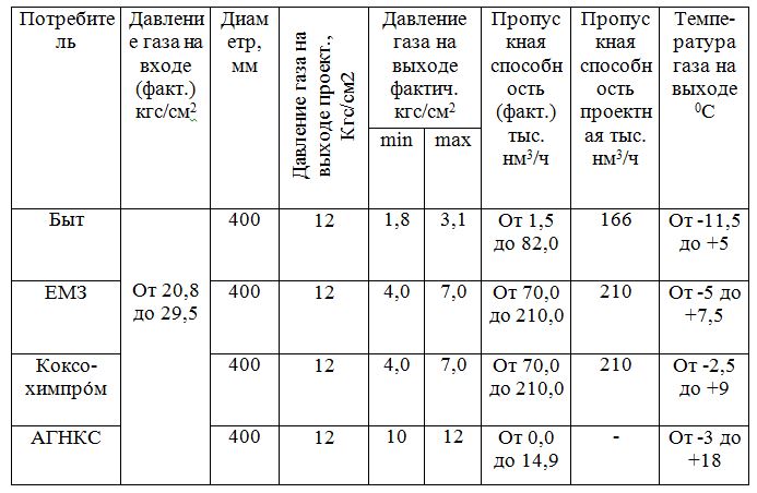
Table 1 – The parameters of gas at the output of GDS for consumers
After reduction, the gas pipelines (for each consumer) are connected and have output manifolds of the following sizes:
Yenakiyevo Coke Plant–
Edge– DU400.
Reduction node has:
9Life– three reduction lines with two RDP-150 regulators and one RDU-100.
The principle of operation of pressure regulators is due to the energy of the working medium (Fig. 1).
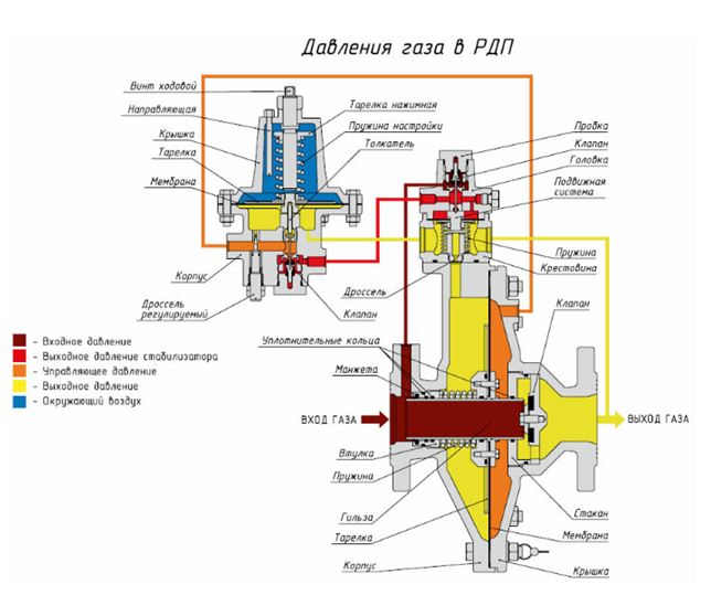
Figure 1 – Scheme of pressure regulators RDP
Inlet pressure enters the actuator and the stabilizer inlet. The stabilizer output pressure is applied to the pilot inlet. In the RDP-B Regulator, the inlet pressure is applied directly to the Pilot inlet. When the pilot's spring is completely free, the pilot's valve is closed. The regulator is switched off. The adjustment of the regulator to a predetermined pressure is made by rotation of the pilot adjustment screw. The pilot opens, the control pressure enters the right cavity of the diaphragm chamber of the actuator. When operating the regulator, the pressure in front of the throttle drops the lines, and therefore in the right cavity of the membrane chamber of the actuator is always above the pressure behind the regulator. The differential pressure on the actuator membrane creates an axial force. The shutter of the regulator opens (the sleeve moves away from the valve). In steady state, the movable elements of the controller are in equilibrium. Any change in the inlet pressure or gas flow causes a change in the outlet pressure and, consequently, in the left cavity of the diaphragm chamber of the actuator, which causes the moving system to move to a new equilibrium state at which the outlet pressure returns to a predetermined value.
At zero gas flow, the pilot and actuator closures are hermetically sealed by increasing the output pressure. In the event of a gas supply to the inlet of the sleeve regulator under the influence of a spring is pressed to the valve. The regulator is closed.
Powder that ends from the hopper into a U-shaped ribbon profile has a non-uniform density due to its heterogeneous particle size distribution. In the table. 1.1 shows the bulk values of fillers used in PP.
An astatic regulator is used in this gas distribution system (Fig. 2).
Figure 2 – Components of astatic regulator: 1 – regulatory (throttle) body; 2 – membrane-loading actuator; 3 – pulse tube; 4 – the object of regulation is the gas network Figure 2 – Schematic of an astatic pressure regulator.
In static controllers, a sensing element (membrane) is subjected to a constant load force 2. Active (counteracting) force is the force perceived by the membrane from the output pressure P2. As the gas extraction from network 4 increases, the pressure P2 will decrease, the balance of forces will be broken, the diaphragm will go down and regulate the body will open. such regulators [1] after perturbation, the regulated pressure is adjusted to the set value regardless of the load and the position of the regulator. The equilibrium of the system can only occur at a setpoint of controlled pressure, and the regulator can take any position. Such regulators should be applied to networks with high self-leveling, for example, in gas networks of low pressure of sufficiently large capacity.
In the considered conditions, the gas pressure regulators of the RDP-150, RDU-50, RDU-40 and 399A Du150 models are equipped with manual control only and are not connected to the ACS. The gas pressure regulators are controlled by the open principle by changing the setpoint manually to maintain the required gas pressure at the outlet of the LPG. The accuracy of maintaining the gas pressure with 0.1 to 0.3 kgf/cm2 is provided by the gas pressure regulator itself.