
Abstract
Contents
- Introduction
- 1. Overview of methods and tools for measuring air flow
- 1.1. Wastewater treatment technology
- 1.2. Differential Pressure Meters
- 1.2.1. General Description
- 1.2.2. Pressure devices
- 1.3. Annubar Averaging Pressure Pipe Characteristic
- 1.3.1. Principle of Operation
- 1.3.2. Advantages
- 1.4 Development of a block diagram and algorithm of work
- Conclusions
- List of sources
Introduction
Currently, the level of environmental pollution by human waste products in densely populated areas reaches a critical point. The main source of water pollution leading to deterioration of water quality is the discharge of industrial wastewater. Currently, many reservoirs of the world due to pollution have lost their importance as sources of fish for economic and sanitary water use. The problem of industrial wastewater treatment and water treatment for technical and drinking needs is becoming increasingly important every year. The difficulty of treatment is associated with the extreme diversity of impurities in the effluent, the amount and composition of which is constantly changing due to the emergence of new industries and a change in existing technology. Currently, the method of wastewater treatment with activated sludge is the most universal and widely used in the treatment of effluents. The use of technical oxygen, highly active symbiotic sludge crops, stimulators of biochemical oxidation, various kinds of advanced designs of aeration tanks, aeration equipment and activated sludge separation systems allowed several times to increase the productivity of the biological treatment method
The wastewater treatment process begins immediately after sewage flows through the sewer system into a treatment plant. Here, thanks to the cleaning method used, the concentration of contaminants and organic impurities in the effluent sharply decreases. Depending on the degree of contamination of the effluents, different cleaning methods or a combination of them are used. The scheme by which the biological wastewater treatment plant will be built depends on this. For this, special microorganisms are used, which in the process of life decompose complex organic compounds into simpler elements (carbon dioxide, water and mineral sediment). Such processing can reduce the concentration of organic pollutants to an acceptable level.
For normal life, activated sludge organisms require small amounts of dissolved oxygen. A critical concentration is considered 0.2 mg, quite satisfactory–0.5 mg of dissolved oxygen. However, activated sludge does not tolerate deposits and, at the slightest stagnation, begins to die from its own metabolites (decay). Therefore, the norms for the content of dissolved oxygen (not less than 1.0–2.0 mg at any point of the aeration tank) suggest providing intensive mixing of the sludge mixture in order to eliminate its deposits. When the concentration of dissolved oxygen exceeds the maximum necessary critical value, the degree of activity of microorganisms does not increase and the purification does not improve. Therefore, for each treatment plant, its own “critical concentration” of oxygen is established, and the degree of its absorption is determined mainly by the nature and concentration of pollution. To adjust the air supply to the aeration tank, flow meters of various operating principles are used.
The aim of the work is to develop an air flow meter for aeration tanks of Donetsk sewage treatment plants. To achieve this goal, the following tasks were formulated and solved: to perform an analytical review of the methods and means of measuring air flow; choose a flow measurement method; to develop a structural diagram and algorithm of work; develop a flowmeter circuit diagram; perform modeling of circuit nodes; estimate the measurement error; design a circuit board and structural elements.
1. Overview of methods and tools for measuring air flow
1.1. Wastewater treatment technology
The technological process of wastewater treatment begins with the flow to gravity collectors at the aeration station into the receiving tray, the receiving tray is designed to distribute the incoming wastewater through three channels leading to the mechanical gratings. The gratings are designed to detain large floating garbage and are installed along the path of water movement obliquely at an angle of 60–70 ° to the horizontal. Further, according to the technological process of wastewater treatment, wastewater flows to horizontal sand traps, where sand and other mineral impurities are extracted from wastewater fineness of at least 0.25 mm. Sand, trapped in the pits of the sand trap section, is removed by a hydraulic elevator via a slurry pipeline to a sand dewatering bin. The settled water from the hopper is transferred via an overflow pipe to the receiving tray in front of the grates, and the sand from the hopper is unloaded to the machine and transported to a landfill. Sand-treated wastewater flows from the sand traps through an open tray to a pre-aerator designed for preliminary aeration of wastewater with atmospheric oxygen with the addition of activated sludge, which contributes to coarsening of suspended solids and their better sedimentation on primary sedimentation tanks. Further, the wastewater enters the distribution tank of the primary sumps, from where it is piped to the center of each sump, and clarified water is collected on the periphery. The clarified wastewater from the primary clarifiers is piped to the upper channel of the clarified aeration tank water. Here aeration of wastewater is carried out in a mixture with activated sludge. During aeration, wastewater contaminants are oxidized due to the activity of activated sludge microorganisms, which are sludge flakes populated by a large number of microorganisms that can mineralize organic wastewater substances. The air continuously supplied to the aeration tanks provides the sludge with oxygen, which is necessary for the vital functions of microorganisms, and also contributes to the chemical oxidation of certain types of pollutants in suspension, colloidal and dissolved state. Thus, aeration tanks must provide biological wastewater treatment during the wastewater treatment process (see Figure 1.1). Aerotenk is a rectangular tank consisting of 4 corridors. Only three sections. In each section, one corridor is reserved for a regenerator. Aerotank works on the principle of a mixer. Air is supplied to the aeration tank from the blower station. Aeration time 11 12 hours. A mixture of wastewater with activated sludge is fed through the tray to the distribution tank of the secondary sumps, from where it is piped into the secondary sumps. Secondary sedimentation tanks serve to separate activated sludge from the waste fluid. They are a round tank in terms of plan.
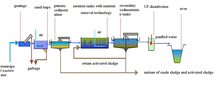
Figure 1.1 – The technological scheme of wastewater treatment
1.2. Differential Pressure Meters
1.2.1. General Description
A flowmeter of variable differential pressure is a measuring complex based on the dependence on the flow of the differential pressure created by a flow transducer installed in the pipeline or an element of the latter (for example, a bend).
The measuring complex includes:
- Primary flow transmitter;
- Primary communication line connecting tubes and auxiliary devices on them;
- The primary measuring device is a differential pressure gauge;
If it is necessary to transmit readings over a considerable distance, these elements are added:
- secondary converter for moving the movable element of the differential pressure gauge into an electric or pneumatic signal;
- secondary communication line electric wires or connecting tubes;
- secondary measuring instrument;
Variable differential pressure flow meters are based on the fact that the flow rate of a substance depends on the differential pressure created by a stationary device installed in the pipeline or by a pipeline element. This group includes flow meters with a narrowing device, with a pressure device, etc. (see fig. 1.2).
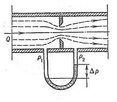
Figure 1.2.1 – Differential Pressure Meter
Dignity:
- simplicity of design, low cost;
- high enough accuracy;
- verification without disassembling to control geometric parameters;
The disadvantages include:
- small dynamic range of measurements (no more than 10);
1.2.2. Pressure devices
Pressure devices create a pressure differential depending on the dynamic pressure of the flow. They transform the kinetic energy of the flow into potential. These devices include pressure pipes, averagers, fenders and amplifiers. Only pressure averagers form a pressure differential depending on the flow rate, and other devices depending on the speed existing in the place of their installation. However, using pressure pipes it is possible to determine the flow rate of liquids and gases.
The advantage of pressure devices: low pressure loss, the ability to measure non-circular sections in pipes and channels, the availability of local velocity measurements in experimental and other works. The disadvantage is very low sensitivity at low speeds.
Pressure pipes. A classic example of a pressure device is a G-shaped tube with an opening directed towards the flow, which is called a Pitot tube by the name of a French scientist who used it to measure the speed of a river. Such a tube perceives the total pressure, which is equal to the sum of the dynamic pd = pv2 / 2 and the static pc of the flow pressure. In order to measure the velocity v in the pipeline using such a tube, it is necessary, in addition to the Pitot tube, to have another tube to take only static pressure pc. Then the differential pressure gauge, which measures the pressure difference, will serve to determine the speed.
In most cases, tubes for sampling the total and static pressures are structurally combined. Such a device is most correctly called a differential pitot tube.
Each of them consists of two tubes, one of which is located concentrically inside the other. The central tube has an open end directed towards the flow. She perceives the full pressure of the RP. static pressure acts through openings located on the cylindrical surface of the outer tube. The axes of these holes are perpendicular to the axis of the tube, and therefore to the direction of the Pitot tube, measures the dynamic pressure, which is equal to the difference between the total and static pressures.
The part of the tube parallel to the axis of the pipeline is called the head, and the holder perpendicular to this axis. The nose of the tube has a streamlined shape: conical, hemispherical or semi ellipsoidal.
Pressure averagers. In pressure averagers, the pressure drop does not depend on local, but on some average dynamic flow pressure. Averaging can be carried out within one, as well as two radii or diameters with an annular area or other methods.
Pressure vane. The pressure device is in the form of a streamlined blade or wing, which occupies a small part of the pipe bore and is installed at a certain angle (usually within 45,900) to the flow axis.
The blade has openings arranged differently with respect to the flow axis. The pressure difference in these holes depends on the angle of installation of the blade, which makes it possible to use this device for measuring flow at low and at high speeds.
Pressure amplifiers are a combination of pressure tubes with narrowing devices (usually micro venturi tubes) that occupy a small portion of the flow cross section. Their appearance is due to the desire to increase the measured pressure drop, which at low flow rates is very small for pressure tubes.
1.3. Annubar Averaging Pressure Feature
1.3.1. Operating principle
As the flow moves through the pipeline, the front wall of the flow body is exposed to the pressure of the process medium. As a result, the dynamic pressure is read out by the groove of the high-pressure chambers of the Annubar tube, through which most of the flow profile passes, allowing for more complete and accurate measurements. Such dynamic pressure is higher than linear static, when the flow passes around the body around the back wall, low pressure is created, it is lower than linear static, low pressure is read by the openings of the negative chamber located on the back wall of the tube. The difference between the high pressure measured on the front wall of the flow around and the low measured on the back wall is the differential pressure that the differential pressure transducer measures (see Figure 1.3.1).
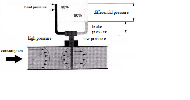
Figure 1.3.1 – Принцип работы осредняющей напорной трубки Аннубар
The composition of the flow meters includes Annubar T-shaped tubes recognized as the best primary elements of flow measurement. The front flat profile of the T-shaped section of the Annubar tube ensures the fixation of the flow separation point, which increases the differential pressure signal and allows measurements to be made over a wider flow range. The location of the openings of the low-pressure chambers in the braking zone on the back of the T-shaped section of the tube provides a reduction in the level of interference of measurement errors causing process oscillations, in addition, this arrangement prevents the ingress of solid particles into the openings of the chamber and eliminates clogging (see Fig. 1.3.2) .
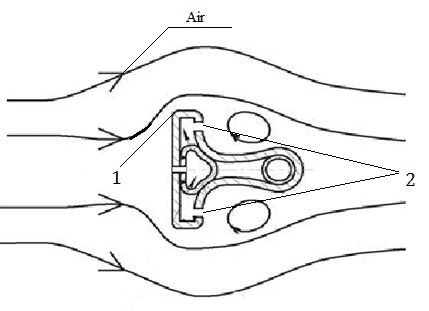
1–Front flat profile; 2–The opening of the low pressure chambers.
Figure 1.3.1 – Annubar T pipe
1.3.2. Advantages
Maximum energy savings Rosemount Annubar ONT flowmeters reduce operating costs. Due to the design of the mediating pressure tube, irretrievable pressure losses are less than when using other primary elements in flowmeters of variable differential pressure. This, in turn, makes it possible to achieve significant energy savings by reducing the cost of energy supply for pumps that pump liquid, the cost of compressing gas and energy to generate steam. This energy savings during operation of Rosemount flowmeters based on Annubar ONT ensures their payback within six months.
Reduced material costs for large piping diameters Rosemount Annubar ONT-based flowmeters require less materials to install, which reduces installation costs and the weight of the flowmeter. Annubar ONT flowmeters are a cost-effective solution for measuring flow rates on large diameter pipelines.
Save time and reduce installation costs Patented Pak Lok ™ mounting is a simple and affordable solution. This type of installation does not require the use of special flanges, which saves money.
1.4 Development of a block diagram and working algorithm
Block diagram of a measuring instrument for measuring air flow (see figure 1.4.1)
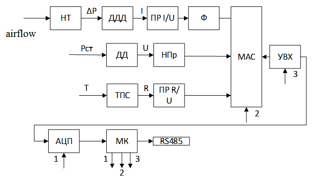
NT Pressure pipe; DDD differential pressure sensor; PRI / U current-voltage converter; DD pressure sensor; NPp normalizing converter; TPS resistance thermal converter; OL R / U resistance-to-voltage converter; MAC multiplexers of analog signals; ADC analog to digital converter; MK microcontroller; RS485 interface UVX device for sampling and storage; Filter; 1 control unit ADC; 2 control unit MAC; 3 control unit UVH.
Figure 1.4.1 Block diagram of the meter
The algorithm of the structural diagram of the measuring device.
The pressure tube measures the difference in pressure of the air flow, the pressure difference enters the differential pressure sensor and is converted into an electric current signal, after the current is supplied to the converter, the voltage and goes to the analog signal multiplexer.
Conclusions
This section provides an overview of the methods and means of measuring air flow. The technology of wastewater treatment, as well as flow meters of variable differential pressure.
The Annubar averaging pressure pipe has been selected, the operating principle of the Annubar pipe and the advantages of the Annubar pipe have been shown.
And a block diagram and flowmeter algorithm were developed.