
Abstract
Content
- Introduction
- 1. Relevance of the topic
- 2. Technological characteristics and operating principle of the heat recovery boiler
- 3. Heat recovery boiler as a control object
- 4. Purpose, functions and objectives of the study
- 5. Development of the ACS concept
- Conclusion
- References
Introduction
Efficient use of secondary energy resources and significant savings on the purchase of fuel for boiler equipment are the most relevant factors, which are considered by large industrial enterprises in all segments of economic activity. Exhaust gases of industrial installations in most they are used idling through cleaning and subsequent release into the atmosphere. Boiler utilizer makes it possible to save money on the purchase and installation boiler equipment, as well as generate solid amounts of heat without the cost of buying energy
1. Relevance of the topic
Improving the efficiency of the use of secondary energy resources can be achieved by improving the operating main and auxiliary equipment of a thermal power plant (TPP), their thermal and start-up circuits, automated technological systems processes (ACS TP) and operation technology, as well as the introduction of new replacement equipment.
Technical and economic indicators of TPP depend on the characteristics of the main equipment and the type of fuel burned, especially when burning different coals, as well as from the technological scheme of heat release. The efficiency of boilers and heat-generating steam-turbine units is of the utmost importance.
Therefore, developments aimed at improving the efficiency of technology for the use of secondary energy resources are relevant. This is especially important for the reconstruction and technical re-equipment of APCS of TPP, the equipment of which has exhausted its resource.
2.Technological characteristics and operating principle of the heat recovery boiler
A heat recovery boiler is a boiler that does not have its own firebox in its design, its principle of operation is based on the use of heat generated in the any production processes, for example, the formation of exhaust gases in the process of generating electricity at a thermal power plant.
The main thermal waste or secondary energy resources are:
- The physical heat of the exhaust gases (sometimes containing chemical or heat).
- Heat of technological production.
- Heat of slag waste.
- Heat of working bodies of systems of forced cooling of technological chambers.
The use of thermal waste in the recovery boiler provides additional products in the form of energy or process steam, hot water, etc., which leads to fuel economy in the enterprise.
The performance of steam, the design of the heat recovery boiler, directly depends on the volume and quality of the gas being disposed of.
In the conditions of the Zuevskaya TPP, gas-tube horizontal heat recovery boilers are used.

Figure 1 – Construction of horizontal gas-tube heat recovery boiler.
1-input chamber; 2-output chamber; 3-superheater pipes; 4-steam separation device;
5-feed water supply; 6-steam collector, 7-evaporation drum
The combustion products (spent process gases) pass inside the pipes placed in the water volume of the drum and are removed to the atmosphere through the outlet chamber. These boilers are characterized by high gas density, easy maintenance and reduced requirements for feed water.
The main drawbacks of this type of heat recovery boilers are the low coefficient of heat utilization of waste heat from technological units of gases (50-60%), low steam volume per unit of the heating surface.

Figure 2 –Heat recovery boiler (General purpose) for waste gas heat recovery
At the Zuevskaya TPP, Electromechanical means of automation of heat recovery boilers are used. They also work on the principle of "on – off". At a minimum water temperature (minimum steam pressure), they set the damper to the position where the in which the boiler communicates with the exhaust manifold of flue gases, and at the maximum temperature (pressure) disconnect the boiler from the exhaust manifold.
The electric motor of Electromechanical control systems drives a special shaft with a screw thread through the reducer. When the motor is turned on, it moves along the screw thread of the shaft and opens or closes the gas damper via a lever.
The minimum temperature (pressure) relay turns the electric motor in the direction of opening the gas valve, and the maximum temperature (pressure) relay, on the contrary, in the direction of closing it.
Therefore, the existing control system for the heat recovery boiler at the Zuevskaya TPP is morally and technically outdated. It does not allow maintaining the set temperature of the heated coolant. In real conditions, the steam temperature at the outlet of the heat recovery boiler will change due to changes in operational factors: feed water; excess air in the furnace; slag screens of the furnace and superheater, etc. This leads to instability of the equipment.
3. Heat recovery boiler as a control object
The efficiency of utilization of exhaust gases is influenced by the heat capacity of the heat recovery boiler, the mode of supply of exhaust gases to it process gases and their temperature. The volume and temperature of the exhaust gases depends on the amount of fuel burned in the boilers of the TPP.
As a result of the heat exchange process in the recovery boiler, the exhaust gas temperature is reduced from t1 to t2. Feedwater it is supplied to the heat recovery boiler from the water treatment unit, having passed the necessary cleaning from hardness and moisture salts. Water vapor is formed at the outlet of the heat recovery boiler. Water temperature t3 at the entrance to the furnace; steam t4 at the exit from the furnace (Fig. 3).

Figure 3 –Diagram of the main heat flows
The main task of managing the heat recovery boiler is The steam temperature at the outlet of the heat recovery boiler depends on (Fig. 4):
— the load of the recovery boiler;
— feed water temperatures;
— cleanliness of the heating surfaces of the heat recovery boiler and superheater;
— from the amount of steam extraction from the heat recovery boiler.

Figure 4 –Heat recovery boiler as a control object
4. Purpose, functions and objectives of the study
The goal is to increase the efficiency of using secondary energy resources by developing a system of automatic management of the heat recovery boiler, which will improve the heating capacity of the waste gas recovery boiler of the thermal power plant.
To achieve this goal, it is necessary that the SAU boiler-utilizer in the conditions of the Zuevskaya TPP performed:
- Information function:
— centralized control and measurement of heat exchange process parameters in the heat recovery boiler;
— exchange of information between computing means of ACS TP TPP;
— formation and issuance of alarm signals, as well as visualization of information in a convenient form for operational personnel on the arm.
- Control function:
— automatic control of the steam temperature at the outlet of the heat recovery boiler;
— emergency shutdown of the heat recovery boiler.
To implement the selected functions, you need to solve the following problems:
- Perform an analysis of the heat and mass transfer process in the waste gas recovery boiler at the TPP.
- Get a mathematical model of the automatic control system of the heat recovery boiler, which will maintain the required steam temperature.
- Develop a functional automation scheme and select modern automation tools to ensure the performance of ACS functions, as well as provide continuous two-way communication with the upper level of the APCS of the TPP.
- To implement the control algorithms on the basis of the selected technical support ACS.
5. Development of the ACS concept
Particular principles of building control systems should take into account the specifics of a particular object of automation, as well as, the main features of the technical implementation, which are reflected in the technical specifications for the designed system.
Let's consider the possible concepts of building a self-propelled gun with a heat recovery boiler, which are used in practice: cascade-connected regulation; regulation by product bypass; regulation by changing the flow rate of heating steam condensate; regulation by changing the the temperature of the hot coolant; regulation by changing the flow rate of the product.
The use of two-circuit ACS significantly improves the quality of regulation of the final temperature of the steam-water mixture, if use the auxiliary variable to select a parameter whose change will be a strong perturbation for the heat exchange process. Often, the exhaust gas flow rate is selected as an auxiliary parameter (Fig. 5).

Figure 5 –Two-circuit ACS of the heating process using as an auxiliary adjustable value:
a) coolant flow rate; b) pressure; с) pressure in the inter-tube space
To regulate systems in which the change in the exhaust gas flow is unacceptable, use the bypass method. The regulating effect in this case is carried out by changing the flow rate of the bypassed product (Fig. 6, a). Since the movement of the regulator on the bypass line still leads to some change in product consumption, with high requirements for the constancy of this flow rate, two membrane actuators of different types are installed.
A similar effect is achieved when installing a three-way mixing valve (Fig. 6, in).

Figure 6 –Temperature control scheme by changing the product flow in the bypass pipeline:
a) with a single valve; b) with two valves; с) with a three-way valve
By-pass regulation improves the dynamic performance of the system, since the heat exchanger is excluded from the control circuit.
Depending on the possible disturbing effects, one of the control schemes shown in Fig. 7. Stabilizing regulators for exhaust gas flow and product flow eliminate disturbances before they enter the system.

Figure 7 –Schemes: regulation of the heating process:
a) with the stabilization of the product flow rate; b) with a change in the product flow rate depending on the final temperature of the product
Analysis of the heat recovery boiler as a control object showed that the disturbances that have the greatest impact on the temperature of the steam on the the output of the boiler can be measured - the temperature of the exhaust gases at the entrance to the boiler and the temperature of the feed water. Therefore it is possible to offer the block diagram of the invariant ACS of the heat recovery boiler and as an auxiliary controlled value to choose the exhaust gas flow rate.
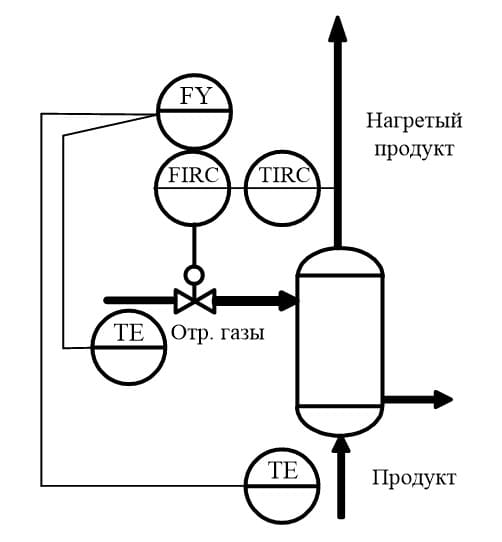
Figure 8 –Combined two-circuit ACS of the heat recovery boiler.
The concept of building distributed control systems has been applied in the development of the automatic control system for the heat recovery boiler based on modern industrial communication protocols with the principle of feedback control.
Conclusion
It is found that the effective use of secondary energy resources is an actual factor, which are considered by large industrial enterprises, including power plants.
It is determined that the efficiency of utilization of exhaust gases depends on the heat capacity of the heat recovery boiler, mode of supply of exhaust process gases and their temperature. The volume and temperature of the exhaust gases depends on the amount of fuel burned in the boilers of the TPP.
The purpose of creating a system of automatic control of the heat recovery boiler in the conditions of the Zuevskaya TPP is formulated, the functions and tasks are described the developed automation system, as well as the main requirements for the integration of the automatic control system of the heat recovery boiler in the hierarchical control system of the TP TPP.
The concept of building distributed systems was applied in the development of the automatic control system for the heat recovery boiler control based on modern industrial communication protocols with the principle of feedback control.
References
- Гудин Г. К., Гребе С. Ф., Сальгадо М. Э. Проектирование систем управления. – М.: БИНОМ. Лаборатория знаний, 2004. – 911 с.
- Измерения в промышленности / справ. изд. под ред. П. Профоса. Пер. с нем. – М., Металлургия, 1980. – 648 с.
- Кафаров В. В., Глебов М. Б. Математическое моделирование основных процессов химических производств: Учеб. пособие для вузов. – М.: Высшая школа, 1991. – 400 с.
- Котлы утилизаторы [Электронный ресурс] – Режим доступа: http://www.energy-gr.com – Дата доступа: 31.03.2018 г.
- Котлы-утилизаторы и энерготехнологические агрегаты / Под ред. Л.Н. Сидельковского / М.: Энергоатомиздат, 1989. - 272 с.
- Клюев А. С., Товарнов А. Г. Наладка систем автоматического регулирования котлоагрегатов. – М.: Энергия, 1970. – 280 с.
- Лазарев Ю. Моделирование процессов и систем в МАТLAB. – СПб.: Питер; Киев: Издательская группа BHV, 2005. – 512 с.
- Ротач В. Я. Теория автоматического управления теплотехническими процессами. –М.: Энергоатомиздат, 1985. – 296 с.