
Content
- Introduction
- 1. Theme urgency
- 2. The purpose and objectives of the study, planned results
- 3. Research and Development Overview
- 3.1 Analysis of VUHP as an automation object
- 3.2 A critical analysis of existing technical solutions for automating the technological process of ventilation of a mine
- 3.3 Functional diagram of VUGP
- 3.4 Block diagram of the control system VUHP
- Operational requirements for the automatic control system VUGP
- conclusions
- References
Introduction
Ventilating mines and mines hazardous in gas and dust is one of the most important objects of automation, since with an ever-increasing degree of mechanization, the intensity of the introduction of mining operations, an increase in the power and depth of mines, which are accompanied by a significant increase in emissions of harmful gases, dust and heat in the mine atmosphere , then the automation of ventilation of mines and mines hazardous in gas and dust will always remain relevant.
The stability and efficiency of the VUHP operation depends on the parameters of the ventilation network, namely, on the general aerodynamic resistance, the amount of air required to be supplied to the mine workings, the natural draft of the network, and other parameters. These parameters, together with the technical characteristics of the fan, determine the operating mode of the fan.
1. Relevance of the topic
Due to the complex feature of the underground coal mining technology, the task of the VUHP automated control system is to supply and distribute the required amount of air over the mine to ensure the required productivity of the faces, compliance with safety rules and sanitary standards, and the normal working conditions of miners.
The master's thesis is devoted to the urgent scientific task of improving the automated control system of the fan of the main ventilation of a coal mine by introducing a control system built on the basis of modern controllers that have shown their relevance in managing complex technological objects such as the process of ventilation of a coal mine.
2. The purpose and objectives of the study, planned results
To increase efficiency by reducing the economic costs of the mine ventilation process, it is necessary to develop an automated control system for the fan installation of the main ventilation of the mine, which will control all the main ventilation parameters and, when their current values deviate from normal values, will control the elements of the ventilation systems.
The developed automated control system should provide control and management of the ventilation process in both normal and emergency operation modes.
In normal operation, the ventilation system must supply and distribute such an amount of air over the mine that, in accordance with the safety rules in coal mines (SB), is required to ensure comfortable and safe working conditions for miners, to ensure a given face performance with existing mine atmosphere parameters: gas emission, dust generation, heat and humidity, with optimal operating conditions of fan installations. In emergency ventilation mode, it is necessary to maintain the parameters of the mine atmosphere within the specified limits and create optimal conditions for the withdrawal of people from the danger zone and the elimination of the accident, its consequences.
3. Research and Development Overview
3.1 Analysis of VUHP as an automation object
Regardless of the purpose, all mine fans are turbomachines–vane machines in which the increase in specific energy, transported air occurs as a result of the force interaction of the blades of a rotating impeller with a stream around them.
Depending on the design of the impeller and the nature of the movement of air through it, mine fans are divided into centrifugal and axial. Both axial and centrifugal fans have their advantages and disadvantages [1].
Figure 1–The technological scheme of VUGP (gif–144 kB, number of frames–4, fps–2 sec.)
Figure 1 shows the following conventions: 1 – main fan, 2 – backup fan, 3,4,5,6,7–lyady, 8–winch, 9–limit switches.
Lyady are necessary for reversing the air stream, for changing productivity, depression are guiding devices that turn their blades depending on the receipt of the necessary parameters. Limit switches are designed to limit the movement of the battery, i.e. if the fret starts to move beyond the specified limit, then the switch to turn off the winch starter for the ship [2].
The requirements for the automation system of the technological process of ventilation of the mine are as follows: 1) local, remote and automated control of fan installations in accordance with the algorithm of operation of the installation in mine conditions; 2) automatic control of the supply of VGP fans; 3) reversal of the ventilation stream of the VGP fan; 4) automatic control and registration of the main parameters of the operation of fan installations; 5) automatic protective shutdown of fan installations in case of violation of their operation modes, in case of violation of the operation of automation equipment, in case of accidents in the power supply system of the installation and in other cases specific to the operating conditions of a particular installation in mine conditions; 6) automatic light and sound alarm in case of emergency. generation of warning messages about emergency situations of ventilation and failures in the automation system; 7) transfer all controlled parameters to the dispatcher’s personal computer, create a database; 8) to visualize the state of the ventilation process and the operation of the automation system of the main fan installation [3].
3.2 A critical analysis of existing technical solutions for automating the technological process of ventilation of a mine.
For automation of fan installations of the main ventilation, the equipment ADShV, UAShV and UKAV–M are used. The ADSHV equipment is designed for remote centralized control of mine fans with low and high voltage asynchronous motors. Functions of the ADSHV equipment: 1) selective centralized control of 12 fans; 2) remote reversal of an air stream of fans; 3) remote opening and closing of the ventilation duct; 4) local fan control; 5) local management of frets and gates; 6) protection of the electric motor from single-phase operation; 7) zero protection; 8) control over the operation mode of the ventilation unit; 9) selective control over the depression developed by the fan; 10) control the correct selection of a fan; 11) automatic continuous emergency (light and sound) signaling in case of a malfunction of any fan, short circuit of the air stream, failure of the electric drive, overheating of the fan motor bearings, local shutdown of the fan, voltage failure, malfunction of the elective and control parts of the equipment; 12) continuous recording of performance and depression; 13) telephone communication between the fan units and the control room; 14) turning off the energy in the area without stopping the pit fan [4].
The UAVSh equipment is designed to automate the main ventilation fan systems and provides control and monitoring of the operation of reversible and non–reversible fans with a high–voltage and low–voltage electric drive. Functions of the UAVSh equipment: 1) telemechanical and local control of two fans; 2) telemechanical and local reversal of the air stream; 3) zero protection; 4) protection of electric motors from single-phase operation; 5) automatic light and sound alarm of controlled parameters. Equipment type UKAV–M is designed to automate the main fan installation in accordance with the requirements for the automation system of the technological process of ventilation of the mine. The UKAV–M set consists of enclosed cabinets and a remote control. The UKAV–M kit is available for one fan unit in several types, differing depending on the type of drive of the fan unit (synchronous, asynchronous or twin-motor synchronous and synchro-asynchronous), the number of drives and auxiliary drives [5].
When analyzing the automation equipment used for the main ventilation fan installation, it can be concluded that none of the above equipment fully satisfies the tasks assigned to it.
3.3 Functional diagram of VUGP
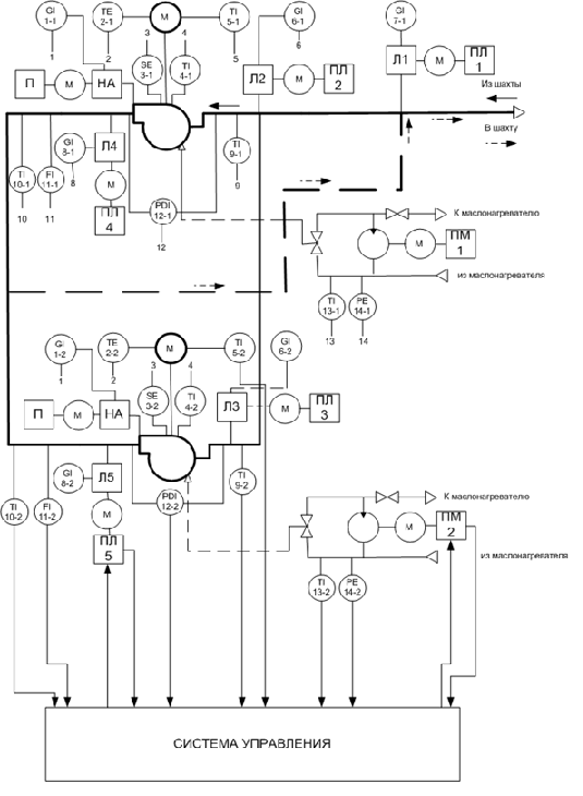
Figure 2 – Functional diagram of VUGP
3.4 Block diagram of the control system VUHP
The block diagram of the automatic control system of the main ventilation fan unit based on the PLC is shown in Figure 3.
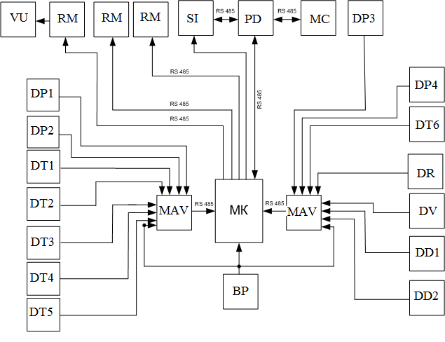
Figure 3 – Block diagram of the control system VUHP
In Figure 3, the following designations are accepted: DD – pressure sensor (air, oil); DP – position sensor, DT – temperature sensor (air, stator windings, oil in the lubrication system, fan bearings, motor bearings); DV – vibration sensor for fan bearings; MK – microcontroller; PD – dispatcher console, SI – light indication and signaling unit, VU – fan unit, PC – industrial computer, MAV – analog input module, RM – output input module with power relays.
The signals from the DD, DT, DR, DV, DP sensors are received through the MAV analog input module, no additional matching blocks are needed for communication between the sensors and the MAV module, then the signals are sent to the MC, the MC processes the incoming data and gives a signal that goes to the PD where the dispatcher may interfere with the process. To power the circuit elements, we use a power supply with an output voltage of + 12V. The communication between the MAV modules and the MK microcontroller is carried out using the RS–485 interface, and the communication between the microcontroller and the dispatcher console, the alarm system and the industrial computer is carried out using the RS–485 interface. To control the guide vanes, frets, oil pump, oil heater, we use the PM module which has power relays to turn on the PME–230 starters. The microcontroller also communicates with the PM module via the RS–485 interface.
Operational requirements for the automatic control system VUGP
When operating the automation system for the technological process of ventilation of mine workings developed in the graduation project, the requirements of the current "Safety Rules in Coals and Mines" and the "Rules for the Technical Operation of Consumer Electrical Installations and the Safety Procedures for the Operation of Consumer Electrical Installations" must be observed [6].
Protective grounding is required for all metal cases of automation equipment of the control system, which in normal operation are not energized, but on which it can appear if the insulation is damaged. Grounding is carried out in accordance with the "Instructions for the device, inspection and measurement of resistance of mine grounding." A systematic monitoring of the state of grounding is established, which is carried out through periodic inspections and measurements of the resistance of the grounding network. According to the instructions, at the beginning of each shift and after each repair of automation equipment, an external inspection of all grounding devices is carried out; at least once a month a thorough inspection and measurement of the total resistance of the grounding network at each ground electrode system, about which a corresponding entry is made in a special book. If any ground fault is detected, the automation equipment must be turned off [6].
Automation system maintenance is carried out in the following terms: 1) routine inspection at least once a day; 2) revision of the launch equipment at least twice a month; 3) checking the correct operation of the equipment during automatic and manual (local) control with subsequent cleaning of relay-contact elements, electrical connections and tuning at least once a month; 4) revision of individual units of equipment with the subsequent replacement of worn elements (parts) and regulation at least twice a year; 5) checking the insulation of cable lines (insulation resistance should be at least 1 megohm) at least once every six months [7].
To exclude cases of electrical injuries during inspections, setting up and operating automation equipment for the control system, service personnel must strictly follow the technical instructions, internal rules and, first of all, know and understand the general provisions for electrical safety. In particular, to avoid cases of touching live parts by using special electro-technical tools with insulated handles, dielectric gloves, rugs, and dielectric galoshes. Only employees who have received special training in the design, installation and commissioning of automation equipment for mine conditions are allowed to service the automation system [6].
Conclusions
In the master's thesis, the modes of operation of the main ventilation fan of a coal mine were considered. It was found that the main ventilation fan works with increased performance and energy overruns. During the analysis, a device was developed to automatically control the performance of the main ventilation fan of a coal mine.
With the improvement of the automated control system for the main ventilation fan, the basic automation equipment was selected, an operating algorithm was developed, circuit solutions for the automation device were developed, and the economic feasibility of introducing an automatic control unit for VUHP capacity at the mine was justified.
When writing this essay, the master's work is not yet completed. Final completion: June 2020. The full text of the work and materials on the topic can be obtained from the author or his leader after the specified date.
List of sources
- Братченко, Б.Ф. Стационарные установки шахт / Под общей ред. Б.Ф.Братченко.—М.: Недра, 1977.—440с.
- Бабак, Г.А. Шахтные вентиляторные установки главного проветривания / К.П. Бочаров, А.Т. Волохов. — М.:Недра,1982.—295 с.
- Богопольский, Б.Х. Автоматизация шахтных вентиляторных установок / М.А. Левин, и др. Изд. 2–е, перераб. и доп.—М.: Недра, 1976.—232 с.
- Волотковский, С.А Электрификация стационарных установок шахт / С.А Волотковский, Д.К. Крюков., Разумный Ю.Т. Справочное пособие / Под.общей ред. Г.Г. Пивняка—М.: Недра,1990—390 с.
- Батицкий, В.А. Автоматизация производственных процессов и АСУ ТП в горной промышленности: учебник [для студентов вузов]. / Батицкий В.А., Куроедов В.И. Рыжков А.А.—М.: Недра, 1991.—303 с.
- Правила безопасности в угольных шахтах [Электронный ресурс]: утв. приказом Гос. Комитета горного и тех. надзора ДНР и Министерством угля и энергетики ДНР 18.04.2016 г. № 36 / 208: ввод в действие 17.05.2016. — Донецк, 2016. — Режим доступа:https://doc.minsvyazdnr.ru.—Загл. с экрана.
- Малиновский, А.К. Автоматизированный электропривод машин и установок шахт и рудников / А.К. Малиновский. — Москва: Недра, 1987. — 280 с.