
Abstract
Abstract on the topic of issue robot
Content
- 1. Relevance of the topic
- 2. The purpose of the master's thesis and research tasks
- 3. Analysis and requirements of the mine pumping station pumping system as an object of automatic control
- 4. Analysis of existing scientific and technical solutions for automation of mine drainage pumping stations
- 4.1 Systems for automatic control of a mine drainage pumping station
- 4.2 Automatic control of the flow of the sump pump station
- 4.3 Automatic control of a drainage pumping station taking into account periods of maximum load of the power system
- 4.4 Automatic cavitation pump protection
- 4.5 Technical metering of electricity consumed by the sump plant
- 5. Some results of theoretical studies to determine the variable parameters and operating modes of an automated pumping station
- 5.1 Justification of the method of coordination of pumping station operating modes during their automatic control
- 5.2 Research on a computer system САР sump installation with a controlled valve
- 5.3 Development of circuit solutions for the automatic control system of a mine drainage pumping station
- References
1. Relevance of the topic
One of the auxiliary technological processes of coal mines is the technological process of drainage. This is a multi–dimensional, multi–connected and energy–intensive process. For many decades and now various scientific and technical workers and organizations have been working to improve the efficiency of the drainage process and the reliability of pumping equipment.
One of the areas of such work is the automation of mine drainage pumping stations. Existing automation systems have several disadvantages in terms of the problem under consideration. The use of modern methods of scientific research, software products and microprocessor technology will substantiate the functionality and develop new, highly efficient automatic control systems for the mine pumping station, so the topic of the master's thesis is relevant.
2. The purpose of the master's thesis and research tasks
The aim of the master's thesis is the scientific justification of the control method and algorithm, and on this basis the creation of an automatic control system for a mine drainage pumping station, increasing its efficiency.
Research Objectives:
- Perform an analysis of the mine drainage pumping station as an object of automatic control and formulate requirements for the automatic control system of the mine drainage pumping station.
- To develop mathematical models for determining the variable parameters and operating conditions of the pumping station, which can be used for automatic control of the mine drainage pumping station.
- To carry out research on a computer system of automatic regulation of the sump installation as an object of automatic control.
- To develop a control algorithm and on its basis to justify the structure and circuit solutions for the automatic control system of a mine drainage pumping station.
3. Analysis and requirements of the mine pumping station pumping system as an object of automatic control
The technological process of mine drainage is designed to remove water from mines to the surface of the mine. Drainage is carried out using drainage plants (a pump with a drive motor and piping). At the mine, the following drainage installations are distinguished: main, water inflows to the surface of the mine from the entire mine, and district, pumping water from the underlying horizons to the upper horizon, where the main pumping station is located. Drainage plants are installed in pumping stations.
There are various drainage schemes [13]. In the master's thesis, the technological scheme of drainage is considered, which is shown in Figure 1. Drainage is carried out from two horizons — hor. 1 and hor. 2. On the horizon of hor. 2, a local pumping station is located (hereinafter referred to as УНС), and on the horizon of hor. 1 there is a main pumping station (ГНС). Drainage is carried out as follows (see Figure 1). Water coming from the faces and the mined–out space is collected into the drainage grooves, through which a pressureless stream, through a preliminary sump (not shown in Figure 1), is sent to the water collector 2 of the УНС pump station. From the catchment 2, water is pumped through the pipeline by a pressure stream to the upper horizon (hor. 1) into the catchment 1 of the pump station of the HPS, the drainage installatiУНС of which pump water to the surface of the mine in a special sump. The main disturbing factor affecting the state of the drainage plant is the mine inflow, which affects the changes in the water level in the catchment, and for the local pumping station, its value in the time interval is not significant, and for the main pumping station, the inflow is determined by the pump flow to the local pumping station, which can be 250m3/h or more.
Design and operation of drainage plants is carried out in accordance with the requirements of the Safety Rules in coal mines [2].
The basic requirements are as follows.
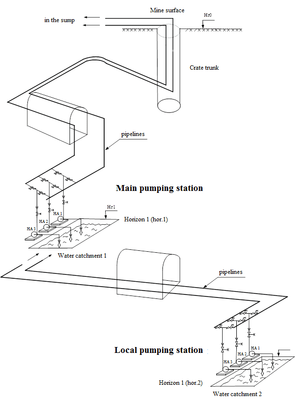
Figure 1 — Technological scheme of mine drainage
The specific number of drainage plants is determined by technical calculation depending on the influx of water. The supply of each pump or group of pumps, not including standby ones, should ensure the pumping out of the maximum daily water inflow in no more than 20 hours.
The main pumping station should have at least two pipelines — a working one and a backup one. The pump is connected to the pipeline using a controlled valve. The catchment capacity of the main pumping station should be designed for at least 4 hours maximum inflow, excluding siltation. The catchment should be maintained in working condition — its siltation should not exceed 30% of the volume.
The local drainage pumping stations also consist of drainage plants and a catchment. The minimum number of drainage plants is one operating and standby. The total number of district drainage plants should be determined by the project. For district pumping stations, it is allowed to have one pipeline. The capacity of the catchment should be designed for at least a 2–hour maximum inflow excluding siltation. The catchment should be maintained in working condition — its siltation should not exceed 30% of the volume.
Sectional centrifugal pumps of the types TsNS, TsNSK, TsNSSh, NShS, etc. are used as pumps for drainage plants [3]. Pump delivery and evolving head have different typical values. The choice of pump supply should be made in accordance with the data on the expected water inflows. As a rule, at district pumping stations, less powerful pumps are used, for example, type TsNS 180–340, i.e. these pumps develop a flow of 180 m3/h and a head of 340 m. of water. pillar. At the main pumping stations, more powerful pumps are used, for example, central nervous system type 360–600.
Drainage pumps operate on a pipeline network with a positive geometric elevation.
Each type of pump has individual operating characteristics, which during the operation of the pump change due to the difficult operating conditions of the pumps when pumping acidic and contaminated water, and, consequently, the values of the pump operating parameters (supply, pressure, efficiency) change, which leads to reduce the efficiency of the sump installation, the occurrence of failures of pumping equipment. Therefore, constant instrumental monitoring of the pump operating parameters, analysis of compliance or deviation of the current values of the parameters from the specified (calculated) values are required.
Analysis of failures and the causes of their occurrence indicate that both sudden and gradual failures occur during the operation of the sump installation [12]. Sudden failures are associated with factory–made defects, installation quality and are detected mainly during the running–in period of the equipment. Gradual failures occur in the operating mode and are associated with operational wear of the nodes of the sump installation. So, in each operating mode of drainage installations there are emergency situations. In particular, the following emergencies may occur during the start–up of a sump installation:
- cavitation in the pump;
- output of the operating mode of the pump from the industrial use zone;
- reduction in flow and pressure below acceptable values;
- rush discharge pipe;
- dangerous water hammer;
- overheating of the bearings of the pump and drive motor;
- motor drive accident.
When the pump unit is stopped, a situation may arise that does not close the valve on the discharge pipe of the main pump and, accordingly, the occurrence of a dangerous hydraulic shock. Dangerous water hammer will destroy the piping network and pump design.
Therefore, constant monitoring of the current operating conditions of the pumping unit, their compliance with the calculated modes is required.
As drive electric motors of pumps, non–adjustable asynchronous squirrel–cage rotor motors of the VAO series are used. For example, for the TsNS 180–340 pump, an electric motor of the VAO2–450–250 / 380–22 U2 type with an explosion protection level of IExdIIBT4, power of 250 kW, rotation speed of 3000 rpm, and a supply voltage of 660 V is used. If the pump is powerful, for example, type TsNS300–600, then high–voltage drive asynchronous motors with a squirrel–cage rotor are used, for example, VAO series VAO2–560–800–2D U2 with an explosion protection level IExdIIBT4, power 800 kW, rotation speed 3000 rpm min, supply voltage 6kV. To control these electric motors, either magnetic starters for a low–voltage electric motor or high–voltage switchgears (high–voltage cells) for a high–voltage electric motor are used. Drainage pumping stations are large electric consumers; their total capacity is on average 20% of the installed mine capacity. Since the drainage plants have a work schedule independent of production technology during the day, the drainage pumping stations can act as consumers of regulators in the mine’s power supply system, turning it on and off can reduce the declared capacity of the enterprise, as well as the irregularity of the load schedule of the power system [3]. Thus, when managing the power supply of the mine, it is necessary to carry out technical accounting of the electricity consumed by the drainage plant, since it is important to know the current values of the energy consumption of the installation in order to use it as a consumer–regulator.
It should also be noted that in the presence of automatic regulation of the operating mode of the sump installation, you can:
- cavitation in the pump
- to increase the technical and economic indicators of drainage as a result of a decrease in the installed capacity of pumping units, and consequently a decrease in capital costs and operating costs for drainage;
- reduce energy costs to overcome the hydraulic resistance in the pipeline as a result of a decrease in the average flow rate;
- to increase the reliability of drainage due to a decrease in the number of unit starts and maintenance of established equipment operating modes.
Thus, the requirements for the automatic control system for the pumping station for the mine sump are as follows:
1. The system must be executed on a microprocessor–based elemental base and have three levels of control:
- the lower level of the system should include field equipment: sensors, actuators, starting equipment;
- the middle level of the system should contain programmable controllers, to the input / output modules of which field equipment should be connected. Data exchange between lower–level equipment and local controllers should be carried out through a wired connection via an electric cable;
- the upper level of the system should contain, which serves to visualize the flow of the technological process of drainage and its management, daily allowance and the formation of archive protocols (in the form of text files) about the values of the operating parameters of the drainage plants and the operation of technological equipment, storing the current daily allowance in the memory of the computer (server) and archival protocols, their viewing and printing.
2. The system should provide three types of management:
- local control, while the control of technological equipment should be carried out from the control panel of the pumping station operator using the buttons on its front panel;
- remote control, with manual control from the mine manager computer using the keypad;
- automatic control, while control should be carried out according to a predetermined algorithm depending on the water level in the catchment, without the intervention of the mine dispatcher.
3. The system must implement:
- turning on and off the switching equipment of the driving motors of the main pumps and the submersible (priming) pump;
- turning on and off the switching equipment of the gate valve’s electric motor (opening, closing the gate) on the discharge pipe of the drainage unit;
- automatic activation of the backup pump in case of worker failure;
- prohibition of starting a faulty pump.
4. The system should automatically control the following parameters and modes:
- inflow of water into the catchment basin;
- analog water level in the catchment basin;
- the presence of water filling the main pumps before turning them on;
- pump flow;
- water pressure in the discharge pipe at the pump outlet;
- suction line vacuum pressure pump;
- technical metering of electricity consumption of a sump plant;
- temperature of the bearings of the pump and drive motor;
- position of the valve on the discharge pipe (open or closed);
- state of switching equipment of the drive motor of the main pump (on, off);
- operating time of the sump installation.
5. The system should provide the following types of protection:
- with the development of cavitation in the pump;
- from overheating of bearings;
- hydraulic protection for water flow;
- when jamming valves;
- the impossibility of restarting a faulty sump installation without the intervention of maintenance personnel.
6. The system should give sound and light alarms about the operating modes of the drainage plant, as well as display information on the light display of the pump station operator about the current water level in the catchment, the presence and types of malfunctions of the drainage plant.
7. The system should transfer data (if necessary, control commands) to (from) an industrial computer on the control panel of the mine’s mine manager to visualize the operation of the pumping station and manage it, create a database, archive data and, if necessary, generate printed forms for a certain period of time.
8.* The system must control the pumping station taking into account periods of maximum load of the power system.
9.* The system should automatically regulate the flow of the sump installation.
10. The system must communicate through the local industrial network with the Systems of other pumping stations, if these stations are hydraulically interconnected.
Requirements marked with an asterisk must be accepted for the automatic control system of the pumping station by a feasibility study for the conditions of a particular mine’s drainage.
So, requirement 8 — control of the pumping station taking into account periods of maximum load of the power system, in our opinion, can be accepted only for the automatic control system of the main pumping station for mine drainage, since it is the most energy–intensive compared to the local pumping station and its shutdown during maximum load in the power system to achieve the desired result. In addition, the catchment of the main pumping station has a larger volume for accumulating water during the period of shutdown of the sump installation.
Requirement 9 — automatic control of the supply of a sump installation can be accepted, in our opinion, only for the automatic control system of a local mine drainage pump station, since the pumps of the main pump station pump water to a height almost as high as possible with the existing pump sizes, which leads to a small regulation depth. Regulation of the supply of the pumping station of the local pumping station will allow you to change the flow of water into the water reservoir of the main pumping station, which in some cases may be necessary, for example, when creating the free volume of the water collector to accumulate water for the period of stopping the pumps of the main pumping station as consumers of power supply system regulators.
4. Analysis of existing scientific and technical solutions for automation of mine drainage pumping stations
4.1 Systems for automatic control of a mine drainage pumping station
Currently, various automatic control systems have been developed for a pumping station for mine drainage. The paper analyzes the functional and hardware capabilities of the main, in our opinion, modern control systems for their use in the considered technological scheme of mine drainage, in particular: Control system for a drainage installation [4]; Equipment for automation of mine drainage type AAV [5]; Automated mine drainage control system, type AUNS [6]; Automated monitoring and control system for a sump installation type ASKU VU [7]; Automated control system for drainage plants and pumping stations ASUV Cascade
[8]; Automated monitoring and control system for main high–voltage, low–voltage and single drainage plants [9]; Automated control system for АСУ Drainage
[10]; Automatic control system for drainage systems such as ASUV [11].
As a result of the analysis, it was established that all control systems are based on a microprocessor–based elemental base and have a three–level control structure, which corresponds to the requirements set for the automatic control of a mine drainage pumping station. However, in terms of functionality, none of the control systems fully complies with the requirements for automatic control of a mine drainage pumping station set in the work. In particular, missing:
- function of automatic regulation of the operating mode of the sump installation;
- pump protection during cavitation development;
- control of analog water level in a catchment basin;
- power consumption control of a sump plant.
Therefore, the development of a new automatic control system for a pumping station for drainage requires scientific and technical justification for the implementation of these functions.
Despite this, the automated control system for the АСУ Drain
can be used to automatically control the main pumping station of the mine sump, since one of the functions of the system is to control the pumps in order to create natural conditions for not being turned on for a period maximum load of the power system. At the same time, in addition to the control system of the АСУ Vodootliv
, a device for automatic protection of the pump from cavitation and a device for controlling the energy consumption of the drainage plant should be used. As mentioned earlier, the device for automatic regulation of the operating mode of the sump installation of the main pumping station is not required.
For the local pumping station, the control system of the АСУ Vodootliv
can also be used. At the same time, in addition to the control system of the АСУ Water drain
, a device for automatic regulation of the operating mode of the sump installation and a power consumption monitoring device for the sump installation should be used.
4.2 Automatic control of the flow of the sump pump station
There are various ways to control the pump [2], в частности:
- pipe throttling;
- discharge of part of the water from the pressure pipe into the catchment;
- supply of the estimated amount of air to the pump inlet;
- smooth change of frequency of rotation of the impeller of the pump.
As a result of the analysis of the effectiveness of applying each of these methods to mine drainage plants, it was found that the most acceptable method due to the simplicity and low cost of implementation is the method of throttling the water flow in the pressure pipe of the pump by regulating the valve. Although this method of regulation has inherent disadvantages, the main of which are:
- increased abrasive wear of the flow part and the regulating body of the throttle;
- significant pressure loss on the throttle when maneuvering the shutter;
- substantially non–linear static characteristic.
There is currently no device for automatically regulating the flow of a drainage installation of a mine pumping station by throttling a pipeline network.
4.3 Automatic control of a drainage pumping station taking into account periods of maximum load of the power system
There are three options for automatic control of a drainage pumping station, taking into account periods of maximum load on the power system [3]:
- forced inclusion of a sump installation with further regulation of the speed of pumping water;
- regulation of the operation of the sump installation at three points;
- forced activation of the sump installation on time.
As a result of the analysis, it was found that the most acceptable way is to force the pumping station of the pump station to be switched on in time.
The essence of the method is as follows. The operating time of the sump installation consists of cycles(Tц). Over time Тз volume catchment Vв filled with water by the influx of water (direct А–В in figure 2). Upon reaching the upper water level in the catchment (point В) automation equipment automatically switches on the sump installation, and water is pumped out of the catchment (cycle Tр, direct Б–В). When the water level in the lower level catchment basin (point B) is reached, the drainage unit automatically shuts down. Next cycle repeats(В–Д’–Ж). At the same time, as can be seen from the graph, the drainage unit operates over time Тм — the time of maximum load on the mine’s power supply system, which leads to excessive consumption of electricity, loss of its quality. Time Тм for the power system are installed in advance, quarterly (seasonally). When applying the control of the sump installation by forced switching on time, the time is pre–set tвкл, upon reaching which the sump installation is switched on regardless of the water level in the catchment and pumps out water (direct Г–Д). Time tвкл selected so that to the beginning of the period Тм the sump was empty or had such a volume of free capacity that, with the pump not working, the sump during Тм not overfilled with water. Тем the operation of the sump installation during the period of maximum load on the mine’s power supply system is most excluded.
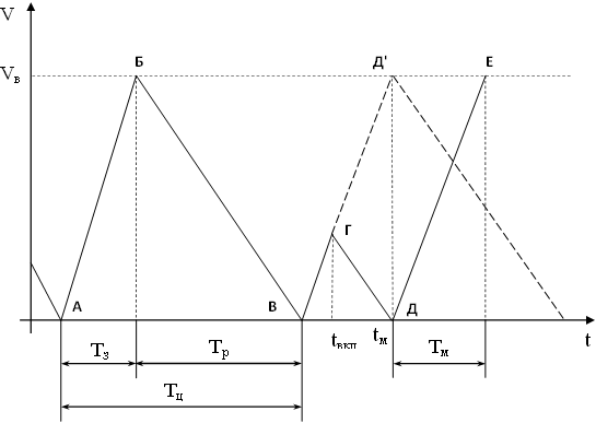
Figure 2 — Schedule of an automated drainage plant taking into account periods of maximum load on the mine’s power supply system
4.4 Automatic cavitation pump protection
As you know, the cause of cavitation is the boiling property of the liquid (phase transition) at normal temperature under low pressure. The appearance of cavitation is facilitated by air dissolved in water, which is released when pressure decreases [14].
At present, there are no sufficiently reliable methods for detecting cavitation that allow you to accurately record the moment of its occurrence. The appearance of cavitation is judged by its secondary features. So, to determine the beginning of cavitation and assess its development, the following methods can be used: energy; vibroacoustic; erosive and visual.
As a result of the analysis, it was found that the energy method is the most suitable for instrumental control. With this method, the beginning of cavitation is considered to be a decrease in the pump supply and an increase in the vacuum pressure in the suction pipe of the pump. It should be noted that the formation of information about the beginning of the development of cavitation is possible when water reaches a certain level in the catchment hк, corresponding to the calculated value of the cavitation stock of the pump used. This is necessary to avoid false triggering during short–term changes in the pump operating mode for other reasons, causing fluctuations in the pump flow and vacuum pressure in the pump suction pipe, for example, when the suction device is clogged. The level hк may be lower than the disconnecting level of the automatic control system of the sump installation, which is achieved by increasing the volume of pumping water by the sump installation.
There is currently no device for automatically protecting the pump of a sump installation from cavitation.
4.5 Technical metering of electricity consumed by the sump plant
To control the drainage installation of the pumping station as a consumer — the regulator of the mine’s power supply system, it is necessary to carry out technical accounting of the electricity consumed by the drainage installation. This type of control can be implemented with appropriate control and measuring devices. However, this is currently a problem, since the drive motor of the sump pump is switched by a high–voltage cell, as a rule, of the KRUV–6 type, in which the number of primary sensors is insufficient to implement standard schemes for measuring the active power consumed by an electric receiver connected to a three–phase electric network mine. So, in the KRUV–6 cell, a TV voltage transformer (type NOL.11–605) with a power of Sl=400 VA is connected, connected to two phases of the high–voltage network, respectively, there is only one secondary line voltage output UAC=100V. For the standard connection of control and measuring devices of power and power consumption (Aron circuit), two line voltage outputs are required. When the KRUV–6 cell is on, the TV load is 7–10% Sн, that is, the mode is close to the idle mode, it follows that the relative TV error will be within 0.5–1%. Also, two current transformers TT1 and TT2 (TOLK–6–1 type) are built into the KRUV–6 cells (TOLK–6–1 type), respectively, there are terminals for two secondary currents (I2A=I2C=0–5A). The load of current transformers are electromagnetic relays of maximum current protection. This load switching circuit leads to a significant decrease in stability and accuracy class TT (approximately 2–3%), which is not acceptable for control and measuring devices of power and power consumption. Thus, with the existing terminal circuit of the KRUV–6 high–voltage cell (secondary voltage output U2AC=100V and current outputs I2A, I2C), ways of non–standard connection of power control and measuring devices to this cell should be justified. Currently, the development of the KRUV — 6 DVMP high–voltage cell is known, which, as indicated in the instruction manual, measures the magnitude of the power consumed by the load and the energy consumption for technical metering of the consumed electricity [11]. However, these cells are not yet used in the mines of the Donbass, and monitoring and accounting for electricity consumption by drainage plants is necessary, which requires a search for scientific and technical solutions to this problem.
5. Some results of theoretical studies to determine the variable parameters and operating modes of an automated pumping station
5.1 Justification of the method of coordination of pumping station operating modes during their automatic control
The work considers the technological scheme of drainage, consisting of a local pumping station and the main pumping station. The diagram is shown in Figure 3. The diagram indicates: ВУ 1 — a drainage installation of a local pumping station; ВУ 2 — sump installation of the main pumping station; Qпр1, Qпр2 — water inflow by a non–pressure flow into the catchment area of the local and main pumping stations, respectively; Q1, Q2 — supply of a sump installation, respectively, of the district and main pumping stations; hн, hв, h(t1) — water level in the catchment area of the local pumping station, respectively lower, upper and intermediate at time t1; Hн, Hв, H(t1) is the water level in the catchment of the main pumping station, respectively, lower, upper and intermediate at time t1.
Unit ВУ 1 is equipped with an automatic control system (САР) of the operating mode of the sump installation.
The following method is proposed for automatically coordinating the operating modes of the main and local drainage pumping stations, including taking into account the period Tmax of the maximum load in the mine’s power supply system for a daily time interval.
Рисунок 3 — Technological scheme of mine drainage
(animation: 10 frames, 5 cycles of repetition, 89 kilobytes)
Activation of the ВУ2 sump installation outside the period Tmax is carried out when the current water level H(t1) is reached in the water collector of level 2 Hв or forcedly by command from the upper control level (mine dispatcher). The operation of the ВУ1 sump installation is carried out when the current water level h(t1) is reached in the water collector of level 1 hв, provided
Turning on the installation of the control unit 1 is performed at the nominal operating mode.
The shutdown of the ВУ1 or ВУ2 drainage plant outside the Tmax period is carried out when the current water level in the corresponding low–level water basin is reached.
When Tmax occurs, the value of H(t1) determines the free volume Vsv(t1) of catchment 1 as
V — total volume in the catchment of the main pumping station;
Vв(t1)=H(t1)S — water–filled reservoir volume of the main pumping station at a time t1;
S — catchment area.
Next, the time to fill with water is calculated Tз water basin 2 volume Vсв (t1) как
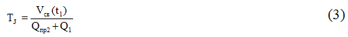
Moreover, if the control value Qпр2 кusually absent, given that the quantity Qпр2 << Q1, value Qпр1can be neglected. Then from the expression (3) it follows that the value Tз determines feed Q1 sump installation ВУ1. Moreover, if the control value Qпр2 usually absent, given that the quantity Qпр2 << Q1, value Qпр1 can be neglected. Then from the expression (3) it follows that the value Tз determines feed Q1 ВУ sump installation1.
Based on the requirement to use the ВУ2 sump installation as a regulator consumer, it is necessary that the ВУ2 installation be turned off during the Tmax time period. Then the condition must be met
Using expression (3), it is possible to calculate the required value of Q 1 and using CAP, change the operating mode of the ВУ1 sump installation (reduce the flow rate by an estimated value) for the period Tmax. At the same time, the sump installation ВУ2 turns off. After the time Tmax sump installation ВУ1transferred to the nominal operating mode.
To simulate changes in the water level in catchment 2 at different flows Q1, a program was developed in the MathCAD package. For example, Figure 4 shows a graph of the change in water level in the catchment of the main pumping station of the mine named after M. I. Kalinina (catchment area S=500 m2) of a horizon of 229 m, into which water is pumped by a district water sump installation of a horizon of 758 m (pump type CNS 300x600).
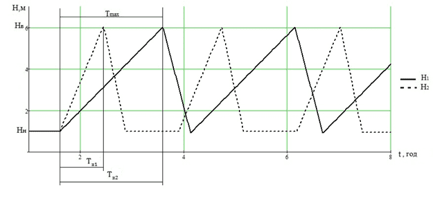
Figure 4 — Graph of changes in water level in the catchment of the main pumping station
Figure 4 indicates: curve H2 — change in water level in the drainage tank of the main pumping station at the nominal flow rate of the district drainage plant Q1=300 m3/h; curve Н1 – the change in water level in the drainage tank of the main pumping station when applying the local drainage plant Q1=210 m3/h; time interval Тз1 the time of filling the water of the main pumping station without regulating the flow of the sump installation of the local pumping station; time interval Тз2 – the time of filling the main pumping station with water by regulating the flow of the drainage plant of the local pumping station.
As can be seen from the above graph, with a decrease in the flow rate of the drainage installation of the local pumping station from 300 m3/h to 210 m3/h, we provide the ability to turn off the drainage installation of the main pumping station stations for the period of maximum load in the power supply system, thereby reducing the energy consumption of the mine by the installed capacity of the drainage plant of the main pumping station. In this case, the catchment of the main pumping station will accumulate water coming from the local pumping station without overfilling.
5.2 Research on a computer system САР sump installation with a controlled valve
The technological scheme of a drainage installation with a controlled valve is shown in the figure 5.
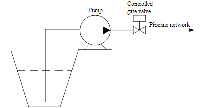
Figure 5 — Technological scheme of a drainage installation with a controlled valve
The functional diagram of the САР system of a drainage installation with a controlled valve installed on the discharge pipe of a drainage installation is shown in the figure 6.
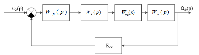
Figure 6 — Functional diagram of the САР system of a drainage installation with a controlled valve
Figure 3 indicates:
1. Wз(р) — transfer function of a controlled valve with electric actuator
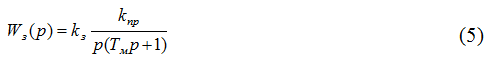
kз — gate resistance coefficient, k=2,5;
kпр — gate valve transmission coefficient (°/В•с), kпр=18;
Tм — time constant, Tм=0,076 с [15].
2. Wтр(р) — transmission function of the pipeline network
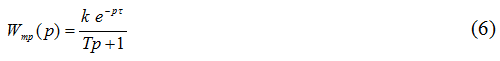
k — gear ratio, k=0,009;
T — time constant, Т=23,55 c;
τ — temporary delay, τ=2,045 c [15].
3. Wн(р) — pump transfer function
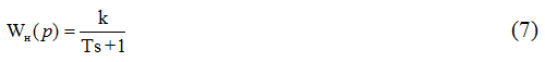
k — gear ratio, k=0,3;
4. Qз(p) — the set value of the flow of the sump installation, which is formed at the upper control level.
5. Qф(p) — Actual discharge value of the sump.
6. Кос — feedback ratio, Кос=1.
The structural diagram of the mathematical description of the САР system of a drainage plant with a controlled valve is shown in the figure 7.
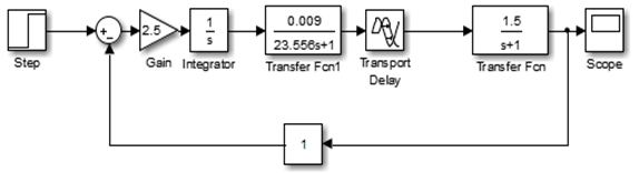
Figure 7 — Structural diagram of the mathematical description of the САР system of a controlled–valve sump
As a result of a computer research of the САР system with various types of controllers, it was found that the most technically acceptable is the PID controller. At the same time, a graph of the transition process is obtained, which is shown in Figure 8.
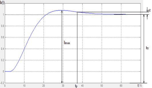
Figure 8 — Schedule of the transition process in the САР of a controlled–valve sump
In accordance with the obtained schedule, the overshoot value is determined:
Transient time tp=37,2 с.
ТThus, the obtained quality indicators of the CAP system of a controlled–valve valve sump satisfy the requirements for the regulatory process — the process is stable, there are no dangerous fluctuations in the output value.
5.3 Development of circuit solutions for the automatic control system of a mine drainage pumping station
In the work, a block diagram of the automatic control system for a mine drainage pumping station for the main pumping station is developed, which is shown in the figure 9.
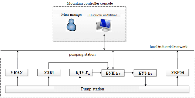
Figure 9 — Block diagram of the automatic control system for a mine drainage pumping station for a main pumping station
The work also developed a structural diagram of an automatic control system for a local mine drainage pump station for a local pump station, which is shown in the figure 10.
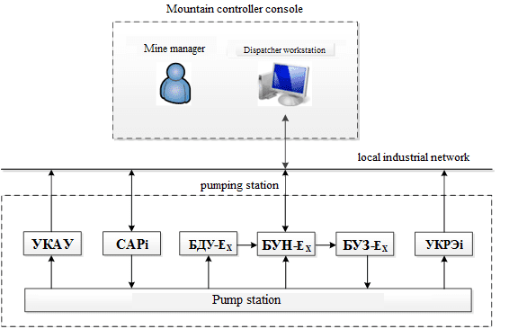
Figure 10 — Block diagram of a system for automatic control of a mine drainage pumping station for a local pumping station
As the basic equipment for the automatic control system of the pumping station for the drainage of the mine, the automatic control equipment Drainage
was adopted.
The system also includes devices: УАКУ — device for automatic control of the analog water level in the catchment (1 pc. to the station); САРi — automatic valve control device (1 pc. for each i–ю sump installation); УКЗ — device for automatic protection of a sump installation from cavitation (1шт. for each i–ю sump installation); УКРЭi — a device for controlling the energy consumption of a drainage plant (1 pc. for each i–ю sump installation).
АСУ equipment Vodootliv
is intended for use in existing, reconstructed and under construction mines hazardous in gas and dust, sudden emissions of coal, gas, and provides, in a typical version, automatic control of up to four pumps with high and low engines voltage [10]. The number of controlled pumps, if necessary, can be increased.
АСУ equipment Drainage
provides:
- control modes: automatic (with the possibility of remote start and stop), manual (semi–automatic, from the automation cabinet) and emergency (direct control of actuators for drainage);
- automatic control of pumping units as a function of water level;
- automatic activation of the backup pump in case of worker failure;
- order of operation of the pumps;
- sequence of starting and stopping pumps during their parallel operation;
- prohibition of starting a faulty pump;
- correction of the pump work schedule in order to create natural conditions for not switching it on for the period of maximum load of the power system;
- accounting of operating time of pumping units;
- display of signals on the dispatcher’s board about the water level in the catchment, pump operation, failure and type of malfunction in the installation, the time period of the maximum load of the power system.
The composition of the АСУ equipment Vodootliv
, is: Dispatcher workstation, located in the control room, and the equipment located in the pump station: sensor unit БДУ–Ex, pump station control unit БУНС–Ex, valve control unit БУЗ–Ex.
The automatic valve control device (CAP) provides a change in the operating mode of the sump installation using a controlled valve installed on the discharge pipe of the installation.
The automatic control device for the analogue water level in the УАКУ water collector monitors the current analogue water level in the water–collector.
The device for automatic protection of a sump installation from cavitation type УКЗ provides control of the development of cavitation in the pump and protection of the sump installation from cavitation.
A device for controlling the energy consumption of a УКРЭ type sump installation provides control and metering of electric power consumption by a sump unit.
Devices УАКУ, УКЗ and УКРЭ are new devices developed in the work, but due to the limited scope of the essay, their development is given in the master's thesis.
References
- Правила безопасности в угольных шахтах [Электронный ресурс]: утв. приказом Гос. Комитета горного и техн. надзора ДНР и М–вом угля и энергетики ДНР от 18.04.2016 г. № 36/208: ввод в действие 17.05.2016. – Донецк, 2016 [Электронный ресурс]. – Режим доступа: http://mintek–dnr.ru/zu....
- Центробежные насосы и трубопроводные сети в горной промышленности : справочное пособие / Ф. А. Папаяни [и др.]; под общ. ред. Ф. А. Папаяни, Н. Б. Трейнера. – Донецк: Восточный издательский дом, 2011. – 334 с.
- Данильчук, Г. И. Автоматизация электропотребления водоотливных устанвок/ Г. И. Данильчук, С. П. Шевчук, П. К. Василенко. – К.: Техника, 1981. – 102 с.
- ООО НПФ
Элкуб
[Электронный ресурс]: офиц. сайт. – Электрон. дан. – Новосибирск, [2019] [Электронный ресурс]. – Режим доступа: http://elcub.ru/. - Частное акционерное общество
ДИГ
[Электронный ресурс]: офиц. сайт. – Электрон. дан. – Запорожье, [2019] [Электронный ресурс]. – Режим доступа: http://www.deg.com.ua. - Производственная компания
Ильма
[Электронный ресурс]: офиц. сайт. – Электрон. дан. – Томск, [2019] [Электронный ресурс]. – Режим доступа: http://ilma–mk.ru. - ФГУП ПО
Север
[Электронный ресурс]: офиц. сайт. – Электрон. дан. – Томск, [2019]. – Режим доступа: http://www.posever.ru. - Производственное предприятие шахтной электроаппаратуры
Шела
[Электронный ресурс]: офиц. сайт. – Электрон. дан. – Киреевск, [2019]. – Режим доступа: http://www.shela71.ru. - ООО
ИНГОРТЕХ
[Электронный ресурс]: офиц. сайт. – Электрон. дан. – Екатеринбург, [2019]. – Режим доступа: http://www.ingortech.ru/. - Компания ДЭП [Электронный ресурс]: офиц. сайт. – Электрон. дан. – Донецк, [2019]. – Режим доступа: http://dep.ru.
- ООО
Научно–производственное предприятие РУДПРОМАВТОМАТИКА
[Электронный ресурс]: офиц. сайт. – Электрон. дан. – Кривой Рог, [2019]. – Режим доступа: http://www.rpa.ua/. - Бессараб, В. И. Управление шахтной водоотливной установкой в аварийных и аномальных режимах работы / В. И. Бессараб, Р. В. Федюн, В. А. Попов // Научные труды Донецкого национального технического университета. Серия:
Вычислительная техника и автоматизация
. Выпуск 106. – Донецк: ДонНТУ, 2006. – 220 с. – С. 26–33. - Бойко, Н. Г. Рудничные (шахтные) водоотливные и вентиляторные установки: конспект / Н. Г. Бойко; Н. Г. Бойко; ДонНТУ, Каф.
Энергомеханические системы
. – Донецк, 2009. – 168 с. - Карелин, В. Я. Кавитационные явления в центробежных и осевых насосах – Москва: Недра, 1975 – 353 с.
- Автоматизация сложных электромеханических объектов энергоемких производств: учебное пособие для вузов / К. Н. Маренич [и др.]; К. Н. Маренич, С. В. Дубинин, Э. К. Никулин и др.; ГВУЗ
ДонНТУ
. – Донецк: ОООТехнопарк ДонГТУ
, 2015. – 237 с.УНИТЕХ