
Abstract
Сontent
- Introduction
- 1. Theme urgency
- 2. The purpose and objectives of the study
- 3. Methodology for solving the problem and current results
- Conclusion
- References
Introduction
One of the best ways to assimilate information is to implement practical tasks using acquired knowledge. Since microprocessor systems were widely used to create automated process control systems, for mastering knowledge in such disciplines as TAU, MCTDS, CAD, ITS, implementation of solutions based on the MPS is necessary. In the field of industrial control systems, the implementation of real practical tasks without proper preparation is fraught with possible economic, human and environmental losses, then the best way to train designers and integrators is to use laboratory stands.
1. Theme urgency
Currently, among the MPS used in industrial control systems, in the first place in terms of prevalence are programmable logic controllers (PLCs) – devices that allow automation of both relatively small objects, for example, coal preparation conveyors at coke plants, and entire production areas, for example , lines or workshops. The complexity and architecture of the designed and implemented ACS depends on the task, the economic capabilities of the customer and the experience of the designers and integrators of the system, but at the same time it practically does not depend, with rare exceptions, on the specific PLC and its manufacturer, since their vast majority are made according to the same principles and differs only in design, available interfaces and software on which the development and operation of this controller is conducted. The main provisions of PLC programming are regulated by the international standardIEC 61131–3, which allows a trained ACS engineer familiar with the languages of this standard or the logic embedded in them to begin to perform tasks on any ACS with a minimum amount of time to familiarize themselves with it.
To realize the ability to manage and monitor systems at an average level, it is necessary to use human–machine interface systems. Two approaches are often used to solve this problem: using a ACS with a built–in graphical interface or using an operator panel – HMI panels.
2.The purpose and objectives of the study
The purpose of creating a stand is to improve the quality of training and the level of training of students in the direction 03/27/04 Management in technical systems
by developing a laboratory stand and a course of laboratory work carried out on it based on automation equipment Owen
.
The main reason for creating a stand based on PLK150–IP320 is the lack of this DNTU. The reason for the development of a new stand, and not the use of the finished one, is the discrepancy with the set requirements.
The stand under development should be able to study the following issues during laboratory work:
1) Application protocols Modbus RTU , Modbus TCP, CoDeSys Gateway in real conditions;
2) learning the work and practical examples of the ACS 150;
3) swelling universal shareware development environment, the CoDeSys;
4) and learning languages of IEC 61131-3 standard;
5) and learning the principles of connection and configuration of various sensors and simple actuators;
6) and learning the principles of developing a graphical interface for the operator through the HMI–panel;
7) and learning the development environment IP320 Configurator
and the principles of organization of communication IP320 .
Methodology for solving the problem and current results
Since among the requirements for the stand being created, high mobility, full wiring of all available interfaces and the availability of interaction tools were put forward, it is rational to choose a pseudo–modular system as a construction concept.
This system allows you to organize interaction with each individual element of the stand – block. Also, this concept allows you to divide the working area into two independent halves – ACS interfaces (Fig. 3.1) and HMI (Fig. 3.2).
It is necessary to single out, as the main conceptual requirements for the stand being developed, that users should be able to make the necessary commutation with their own hands and that, to use all available capabilities of the ACS and IP320, standard simple means of interaction with all existing interfaces should be provided.
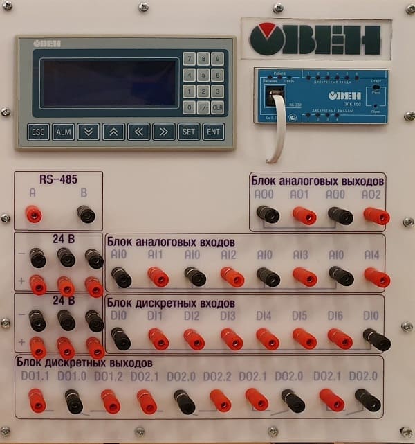
Figure 3.1 – Half of the working area of the stand with ACS interfaces
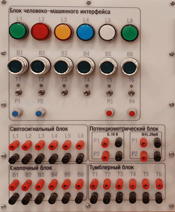
Figure 3.2 – Half the working area of the stand with HMI
All connections on the front panel are made using the JS–910B–1 terminals, and on the side – DB9F. Each connection located on the front panel consists of 2–3 terminals depending on the type of connection, but some, such as 24V, simply have duplicate pairs.
On the side panel are the interfaces:
1) RS–485–duplicates the connection common to the stand via the RS–485 interface ;
2) Ethernet – is the interface of the same name located on the ACS150 ;
3) IP320–RS–232 interface for programming the IP320 panel. Access is possible only after the toggle switch is in the P
position ;
4) ACS150 – RS–232 interface for programming and debugging a program on the ACS150.
Since IP320 for changing the programming and operating mode requires not only changing the interfaces, but also switching the power for this, a three–position industrial type toggle switch with a zero position is provided on the side panel (Fig. 3.3). The P
position connects the IP320 via the RS 485 interface to the common bus of the stand for operation, 0
– disconnects the interfaces and power from the panel, P
– connects the power and the RS–232 interface for programming.
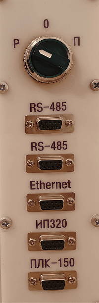
Figure 3.3 – Side panel of interfaces and their switching
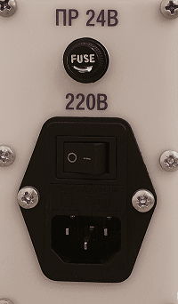
Figure 3.4 – Side power panel on the stand
In the half shown in Figure 3.1, the available interfaces are completely wired and divided into blocks:
1) RS–485;
2) block of analog outputs;
3) block of analog inputs;
4) discrete input block;
5) block of discrete outputs;
6) power supply 24V.
All interface blocks that belong to the ACS interface completely duplicate the visual design located on the part of the ACS hidden under the front panel.
Half of the HMI (Fig. 3.2) can be divided into two parts – switching and interaction. On the part of the interaction are located:
1) 6 industrial indicators of various colors;
2) 6 buttons without fixing an industrial design;
3) 6 toggle switches in two positions with fixation;
4) 4 potentiometers for controlling 0 ... 10V and 4 .. 20mA switches.
On the switching part, terminal blocks are divided into blocks with corresponding designations of additional parameters.
Conclusion
As an object of development, an ACS stand was chosen based on a combination of PKL150–IP320.
The analysis of existing solutions, as well as the requirements that we put forward for the stand being developed, allowed us to create and realize the stand concept in reality.
With the help of practical experience, it was possible to advance, structure and implement the developed device.
When writing this essay, the master's degree is not yet complete. Final completion: June 2019. The full text of the work and materials on the topic can be obtained from the author or his supervisor after this date.
References
- Проектирование средств автоматизации в Санкт–Петербурге и Ленинградской области [Электронный ресурс] URL:https://elektro-78.ru... .
- Учебный лабораторный стенд [Электронный ресурс] URL:https://owen.ru... .
- Промышленная автоматика ОВЕН - 3. Исполнение моноблочное с ноутбуком.ПА-ОВЕН-3-МН [Электронный ресурс] URL:http://www.uralstend.ru... .