
Abstract
Content
- Introduction
- 1. Relevance of the topic
- 2. Convolutional networks
- 3. Mathematical model of AM.
- 4. Results of AM modeling.
- 5. Convolutional neural network
- The list of sources
Introduction
Currently, drive systems based on AC motors play a key role in industrial applications. It is estimated that these machines account for approximately 29% of global and 69% of industrial electricity consumption. When operating electric motors in industrial drive systems, various defects may occur that prevent further operation of the machine. According to statistics, the most common defects in electrical machines are damage to the stator (37%), rotor (10%) and bearing (41%). Static tests show that with an increase in the rated power of electric motors, the role of mechanical damage in favor of electric ones decreases. This fact means that many research centers are focused on developing diagnostic methods that can partially reduce the amount of electrical damage or identify the condition of the machine (incipient malfunction), in which it can still be repaired.
The basis for the operation of diagnostic systems is a thorough knowledge of the changes that occur in the car as a result of damage. Monitoring of changes occurring in AC machines is carried out using signals available for measurement at the object under study. The most commonly used are currents, voltages, vibrations, and flow and temperature. The idea of analytical methods for assessing the technical condition of the machine is based on the identification of signs of damage in the measured diagnostic signals.
The use of an analytical approach in the process of detecting faults in the electric windings of AC motors is associated with the need to adjust the measurement parameters of the diagnostic signal to the method of detecting fault signs. Currently used analytical methods for detecting damage are based on observing changes in the signal in the time, frequency, or frequency-time domain. Among them, the following methods deserve special attention: fast Fourier transform (FFT), advanced vector Park analysis, short-time Fourier transform, Hilbert – Huang transform, and wavelet analysis in the form of continuous wavelet transform or discrete wavelet transform. Of the methods presented, the most common is the use of FFT analysis. Signal spectrum analysis provides both an effective assessment of damage symptoms and does not create a significant load on computing systems. However, like most analytical methods, FFT requires a relatively long measurement time, which, especially in the case of inter-turn short circuits of the stator winding, is an undoubted disadvantage of this method due to the dynamics of these faults. in addition, in many cases it is not possible to ensure the stationarity of the signal during the required measurement period.
Recognition of changes in diagnostic signals and their evaluation in systems based on analytical methods are usually performed by a person, which increases the time of fault detection. Moreover, such systems are often not fully automated, and the number of errors is often related to the experience of a human expert.[3-4]
1. Relevance of the topic
Currently, due to the dynamic development of artificial intelligence methods, diagnostic systems based on analytical methods are gradually being replaced by neural damage detectors. The undoubted advantage of such systems is the limited role of a human expert in the process of assessing the technical condition of the object, while ensuring high efficiency of fault detection. Analytical methods are the basis for the functioning of diagnostic systems based on neural networks (NNS), which are also used for detecting and classifying faults in asynchronous motors. Therefore, the input information for such systems is the result of extracting symptoms from selected diagnostic signals using analytical methods.
Multi-layer neural networks are the most popular structures used in diagnostic methods, including in the case of detecting faults in asynchronous and synchronous motors. In addition to data approximation capabilities, damage classification is a particularly important task of neural network-based diagnostic systems. The main representative of classifiers used in fault detection processes is the Kohonen self-organizing network. The advantage of some of them is its simple structure and the fact that there is no need to provide multiple training samples.
Artificial intelligence methods are increasingly associated with the problem of deep learning. The basis of the structures of deep learning based on classical neural networks. However, deep neural networks (DNN) are characterized by features that differ from classical shallow networks, which is the result of the rejection of the universal approximation rule. The structures used so far, which have a maximum of two hidden layers, have allowed us to achieve satisfactory results. however, the increase in the structure allowed us to obtain features of neural networks that were previously unattainable in classical shallow structures.
For a long time, DNN were used mainly in information systems (for example, image processing, speech recognition). Recently, there has been a growing interest in systems for detecting damage to electrical machines based on DNN. In most cases, they are related to the analysis of mechanical damage or mechanical components of the system. A small amount of work related to electrical damage to the engine is mainly related to damage to the rotor. Most of the systems based on DNN use measurements of vibration, at least the stator currents and voltages. This fact follows from the obvious changes that occur in the diagnosed signal due to mechanical damage and the resulting simplicity of signal analysis.[1-2]/p>
2. Convolutional networks
Among the deep learning network structures used, convolutional neural networks (CNN) are the most commonly used. SNS used in diagnostic applications are characterized by a significantly higher level of efficiency compared to other networks. In diagnostic processes, the CNN can act as a damage classification system, as well as provide information about the degree of damage. An important aspect when using DNN in diagnostic processes is the appropriate adjustment of the measured signal to the structure and properties of the network. the input gnn vector can be obtained by analyzing the signal and directly providing the diagnostic signal. due to the principle of operation of deep learning structures, in most cases the measured signal is converted into a 2d or 3d matrix.
In this paper, the possibility of using CNN in the process of detecting phase asymmetry is presented. The developed application is characterized by direct processing of the raw diagnostic signal. Here, signs of damage are extracted directly from the stator phase current signals, omitting well-known analytical preprocessing methods such as FFT, wavelet, and other higher-order transformations.
The idea of a diagnostic system based on the CNN that performs the task of detecting faults and evaluating the degree of asymmetry of the stator windings is described. In contrast to the methods based on a simple analysis of the vibration signal for detecting mechanical damage, the developed method consists in direct processing of phase current signals through the DNN, which is one of the new approaches in stator fault detection systems.
it should be emphasized that the development of a diagnostic system based on direct analysis of the stator current is associated with additional difficulties due to the fact that voltage asymmetry and damage to the winding causes a similar effect as an increase in the load moment, that is, an increase in the amplitude of the stator current. However, the diagnostic system must detect damage characteristics, i.e. distinguish between the effect of non-symmetry and the effect of drive operating conditions on the analyzed diagnostic signal. [5]
The main function of the CNN is to extract higher-order features from the analyzed signal using convolutional operations. These networks do not have a pre-defined architecture, parameter selection methods, or rules regarding the number of convolutional layers.
The structure of the CNN should be considered as the definition of features that progress with each additional convolutional layer. In the presented CNN in the diagnostic process of the first layer can be used as a filter of the main features, for example, maximum or minimum values. Then the subsequent execution of the convolution operation allows you to detect signs of a higher order, that is, the distance between the minimum and maximum values. Thus, the structure of the network will depend on the type of information provided, as well as on the function performed by the CNN.
To detect complex objects, structures consisting of several sets of layers are used. the ability to detect features is related to the process of acquiring generalization skills by the network. Due to the extensive structure of the CNN, methods that avoid overcompliance become very important.[6]
3. Mathematical model of AD.
The input data for the CNN is the phase currents of the asynchronous motor. To get them, we use a model created in Matlab. However, standard blocks are not suitable for modeling non-symmetry in AD, since they transform to a rotating coordinate system dq, which leads to the loss of important information for training the neural network.
The system of differential equations (DE) of the electric equilibrium of the stator and rotor circuits of an asynchronous motor (AM) for instantaneous values of voltages, currents and flow links, compiled taking into account the assumptions, in matrix form has the form:
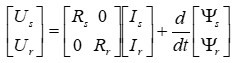
Figure 1 – System of differential equations of electrical equilibrium of the stator and rotor circuits of an asynchronous motor
where
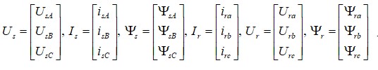
Vectors of voltages, currents and flow couplings of phases A, B, C of the stator and a, b, C of the rotor
Vectors of voltages, currents and flow couplings of phases A, B, C of the stator and a, b, c of the rotor
Rs=diag([rsa rsb rsc ]), Rr=diag([Rra Rrb Rrc ]) – diagonal active resistance matrices of the stator and rotor phases, respectively, reduced to the stator;
Under the condition of complete symmetry of the AD (rsa=rsb=rsc=Rs, Rra =Rrb=Rrc=Rr), the equation (Fig. 1) can be divided into two equations – the voltage balances of the stator and rotor separately-then the active resistance matrices Rs and Rr can be replaced by the corresponding scalar values.
The equation of motion of an EP based on an engine whose rotor rotates, which does not take into account the possible presence of elastic forces, has the form:
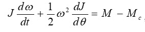
Figure 3 – The Equation of motion ED
where J is the total moment of inertia of the EMC given to the motor shaft, which in General is a function of the angular position of the rotor θ
Mc – total static load moment, consists of the actual load moment on the motor shaft and the dry friction moment, etc.
In cases where the moment of inertia is not a function of the angular position of the rotor, the General equation of motion is somewhat simplified and takes the form:
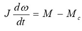
Figure 4 – Equation of motion of the ED in cases when the moment of inertia is not a function of the angular position of the rotor
The AM equations in phase coordinates describe processes in an asynchronous machine, while allowing you to not deviate from the physical essence of these processes. Using this model, it is also possible to conduct a qualitative study of AD operation under conditions of AM asymmetry or power supply (standard asymmetry or asymmetric modes), when AM is powered from a non-ideal power source (non-sinusoidal voltage source).
however, such a model is characterized by the disadvantage that it contains periodic coefficients in the du, which makes it impossible to solve them analytically and significantly increases the duration of their numerical solution
to create an interactive mathematical model, refer to the Matlab application package. The ability of many blocks of the Simulink program, in addition to the Integrator block, to process vector signals, allows you to create a very compact and visual model of AM in a three-phase coordinate system. This is also facilitated by the presence in Simulink of the Matlab Fcn block of the functions&Tables library, which creates an interface between Matlab functions and the Simulink extension.
The block diagram of AM in phase coordinates, based on the equations above, is shown in Figure 5
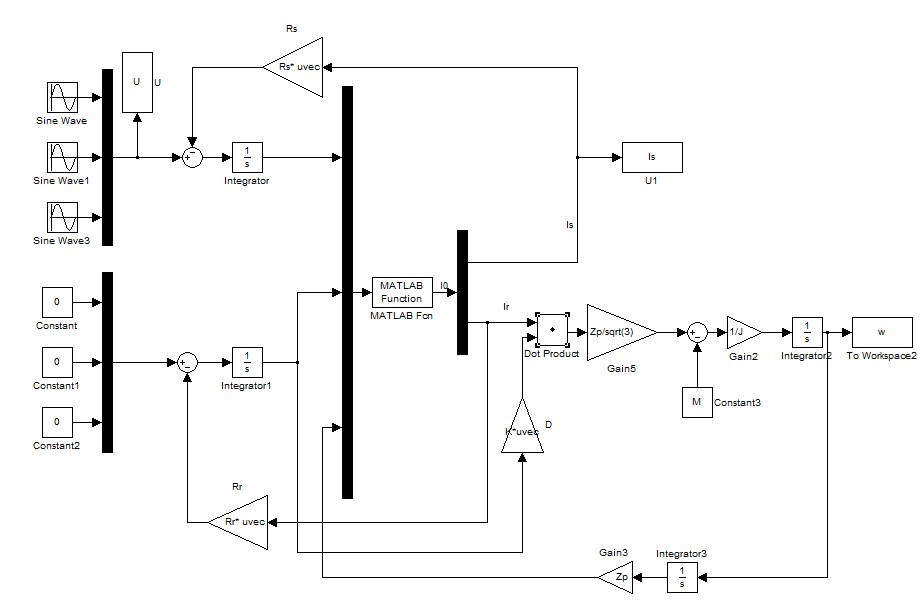
Figure 5 – AM Model
4. Results of AD modeling.
Let's examine an asynchronous motor in several States. Initially, we will model the AM in normal mode, when the resistances of the stator windings are equal. The results are shown in figures 6 and 7
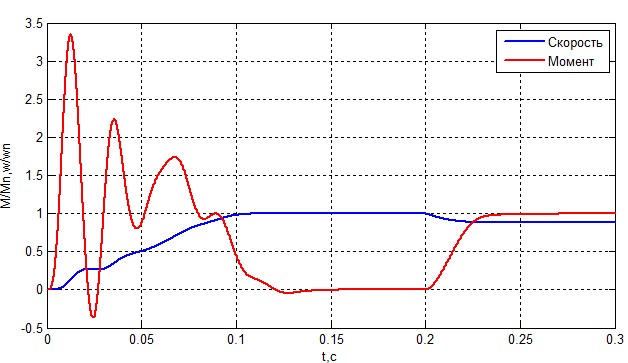
Figure 6 – Speed and moment of AM.
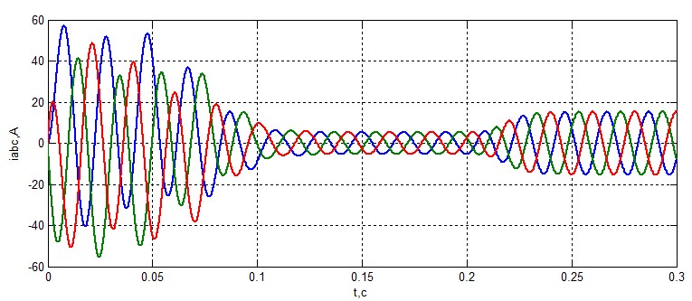
Figure 7 – Stator Current.
The graphs show that the model works and corresponds to reality. You can also extract graphs of the rotor current from it, but they are not useful in this work.
The next step is to model the resistance asymmetry of the stator windings. Change the resistance of the phase a winding by 1% (Fig. 8, 9) and 5% (Fig. 10, 11).
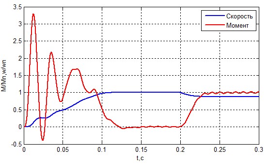
Figure 8 – Speed and moment of AD at ZsA=1.01 Zs.
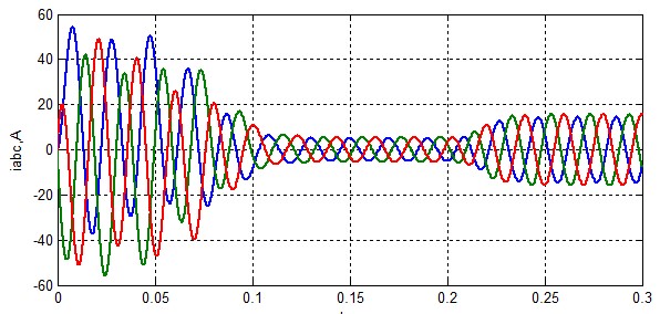
Figure 9 – Stator Current at ZsA=1.01 ZsA.
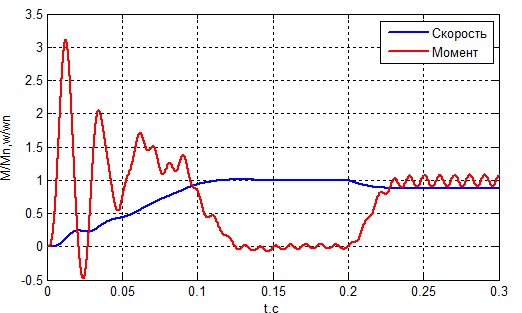
Figure 10 – Speed and moment of AD at ZsA=1.05 ZsA
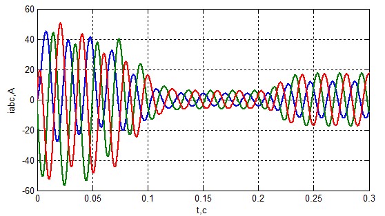
Figure 11& – Stator Current at ZsA=1.05 ZsA
From the graphs above, it follows that the asymmetry in the stator winding is very dangerous for the engine. At one percent of the deviation, the difference is not obvious, but at five percent, the effect of non-symmetry is clearly visible. It leads to engine overload and a shorter service life. It can also lead to aging of the insulation, which will lead to other emergencies later.
5. Convolutional neural network
To classify the non-symmetry in the stator winding, this paper uses a convolutional neural network. The input data for this network is the stator current, and the output data is the motor state.
To create a neural network, I use the built-in Matlab Deep Network Designer library. It is a block editor for neural networks. All the necessary components for a convolutional neural network are available here.
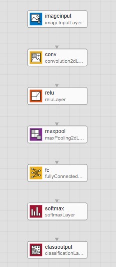
Figure 12 – Convolutional neural network in the editor.
Let's analyze the components of the CNN:
- imageinput is a block of the input layer of the neural network. Its parameters specify the number of inputs. in this case, the matrix is 50x40x3 (rgb matrix), that is, six thousand inputs.
- conv is directly a convolution block. Its parameters specify the number of ultra-precise filters, their size and step in the input matrix.
- relu is a rectification function, the same as the activation function, but it increases the learning rate by an order of magnitude in relation to the normal sigmoid.
- maxpool is the sub-selection layer. The function of this layer is to compress the received input data according to a certain law, in this case, by the maximum value. This allows you to discard the noise and skip the useful signal.
- fc is a fully connected layer. In this layer, each signal of the output layer is connected to all the neurons of the input layer. Each such relationship has its own weight, and these weights will be adjusted during training.
- softmax is a block that creates output layers so that their sum is always equal to one.
- classoutput this block performs conversions from probabilistic to class-based.
Before training a neural network, you need to prepare the input data. In our case, we need to convert three stator currents into one RGB matrix of 50x40x3 size.
The approach in this case is simple. We remove two thousand current points of each phase. The graphs are taken at nominal speed and torque in steady-state mode to simplify network training. We transform each current vector into a 50x40 matrix and compose all three into one three-dimensional array. It is important that the current changes are in the range from 0 to 255, since the RGB matrix contains data of the uint32 type. Next, for clarity, we transform these matrices into images of Fig. 13 and 14
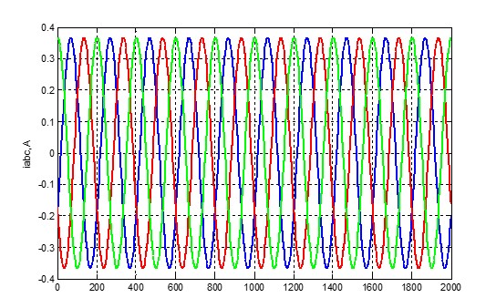
Figure 13 – Convolutional neural network in the editor.

Figure 14 – Convolutional neural network in the editor.
(animation 7 frames, 7 repetition cycles, 6.12 kilobytes)< / br>
The simplest case is used for training. Determination of non-symmetry in one phase. To train the network, you need to use another library called Transfer Learning. It allows you to easily and quickly train the CNN.
For training, the graphs of a healthy engine, and an engine with non-symmetry in phase A. One data packet for a healthy engine, and 5 data packets for a damaged one were taken. This is done to speed up network learning.
After the network has been trained, we import it into the Matlab environment, after which it can be used. You can call the neural network with two commands:
- Classify-this command outputs the response in string form.
- Predict-this command outputs the response in matrix form.
Let's check our CNN. To do this, we will first send the data package to the engines. Then a data packet with non-symmetry in phase A.
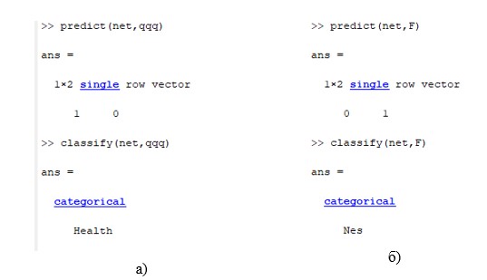
Figure 15 – Demonstration of the neural network. a) healthy engine; b) asymmetry in phase A.
As you can see, the neural network copes with its task very well, even if there was little data for training. In the future, I plan to increase the number of classified faults and make the network work online.
List of sources
- Skowron M. Convolutional neural network-based stator current data-driven incipient stator fault diagnosis of inverter-fed induction motor / M. Skowron, T. Orlowska-Kowalska, M. Wolkiewicz, C. Kowalski // Energies 2020, 13(6) – p. 21.
- Chattopadhyay P. Deep learning in fault diagnosis of induction motor drives / P. Chattopadhyay, C. Delpha, N. Saha, J. Sil // Prognostics and system health management conference 2018 – p. 1064 – 1073.
- Jawadekar A. Arti?cial neural network-based induction motor fault classier using continuous wavelet transform / A. Jawadekar, S. Paraskar, S. Jadhav, G. Dhole // Systems science & control engineering: an open access journal 2014 – p. 684 – 690.
- Jigyasu R. Multiple Faults Diagnosis of Induction Motor Using Artificial Neural Network / R. Jigyasu, L. Mathew, A. Sharma \\ Springer Nature Singapore Pte Ltd. 2019 – p. 701 – 710.
- Lee J.H. Fault Diagnosis of Induction Motor Using Convolutional Neural Network / J.H. Lee, J.H. Pack, I.S. Lee \\ Appl. Sci. 2019, 9(15) – p.10.
- Gupta K. A Review on Fault Diagnosis of Induction Motor using Artificial Neural Networks / K. Gupta, A. Kaur \\ International Journal of Science and Research 2014 – p. 680 – 684.
- Lee K.M. Fault Diagnosis of Induction Motors Based on RBF Neural Network / K.M. Lee, P. Yarlagadda, Y.M. Lu\\ Applied Mechanics and Materials Vols. 462 – 463 2014 p. 85 – 88.