Abstract
Content
- Introduction
- 1. Theme urgency
- 2. Goal and tasks of the research
- 3. Design of the robot manipulator
- 4. Define the settings for the motor selection
- 5. The kinematics of the robot
- 6. MBED OS Real-time Operating System Overview
- Conclusion
- References
Introduction
Over the past few years, microprocessor technology has been developing very rapidly, and new solutions are emerging that allow us to develop more efficient control systems. In addition, power electronics and microcontrollers are becoming cheaper, they are becoming more accessible for use in various projects, and there are great opportunities for developing new electric drive control systems, as well as for improving and automating existing systems.
The development of a slightly complex device using a microcontroller requires a fairly deep knowledge of programming, the internal structure of the microcontroller and the principles of its operation. Such a high entry threshold repels many who would like to start developing embedded systems.
An example of a modern automatic system is robots–manipulators, which are widely used in industry, as well as in dangerous or inaccessible places.
In this paper, we consider a three–link robot manipulator mounted on a movable base, which gives it a number of advantages.
The robot was designed using the SolidWorks program, which allows you to create assemblies and calculate weight and size indicators, taking into account the material from which the parts are made. Simulation of manipulator movements in order to obtain data on the necessary moments acting in the joints was performed in the MATLAB software package in the SimMechanics application.
The robot is controlled using the STM32F4 board. The control system was built in the Waijung Blockset application, which allows you to create and convert models made using conventional Simulink blocks into program code running on the STM32 microcontroller.
In this paper, we will also consider the real-time operating system MBED OS, designed for creating multithreaded programs on 32-bit microcontrollers.
1. Theme urgency
At the moment, ground mobile robots–manipulators are very popular in various fields of activity. Being, in fact, receivers of electric energy, they allow you to perform various types of work in dangerous or hard-to-reach places for humans. At the same time, manipulators are the most important parts of such mobile platforms.
2. Goal and tasks of the research
The goal of the work is to develop a similar manipulator with three degrees of freedom for installation on a mobile platform, as well as to create a control system using different approaches to development.
3. Design of the robot manipulator
Before assembling the manipulator structure in reality, it was designed in the SolidWorks solid-state modeling software package. This program allows you to assemble individual parts and takes into account the material from which individual elements will be made, which makes it possible to automatically calculate the mass characteristics of individual parts and assemblies as a whole[4-5].
The dimensions of all parts of the manipulator structure are selected based on the possibility of its normal installation on a platform with crawler traction. The overall dimensions of the platform are known. When building the assembly, the size and weight of the installed engines were also taken into account.
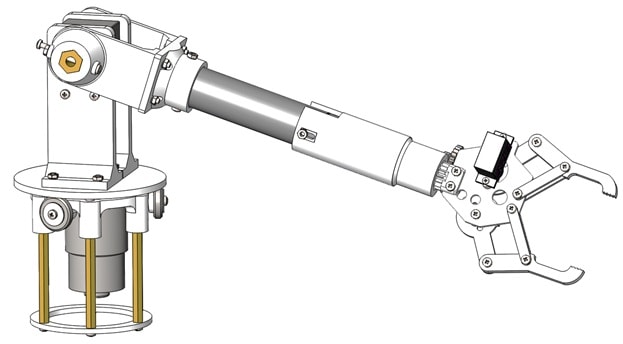
The general view of the resulting manipulator is shown in figure 3.1.

Figure 3.1 — General view of the manipulator (build in SolidWorks)
After developing the project in SolidWorks, the manipulator was assembled "live". Most of the parts were printed with the help of a 3d printer.
4. Define the settings for the motor selection
After creating the project in the SolidWorks program, it was necessary to find the torques acting in each of the joints, determine the required speeds, and based on this data, select the appropriate motors.
To do this, a manipulator model was built in the SimMechanics library of the Simulink package of the Matlab development environment. This library allows you to create models of various objects, taking into account their size and physical properties, which greatly simplifies the creation and modeling of complex mechanical systems, since their mathematical description is not required. The second generation of the SimMechanics application was used in the work[6-7].

Figure 4.1 — Simulation of manipulator movement
(animation: 8 frames, 6 cycles, 147 KB)
A position setter was used to generate the task signal, since it generates a signal that already contains information about the speed and acceleration limit levels.

Figure 4.2 — Block diagram of the position setter
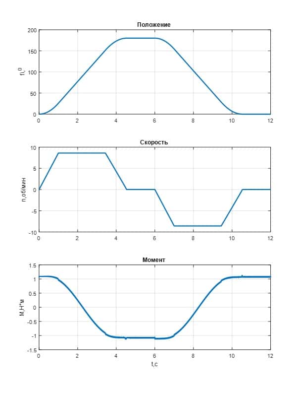
As a result of modeling, it was possible to obtain pictures of the position, velocity and torques acting in the joints.

Figure 4.3 — The resulting graphs
5. The kinematics of the robot
The task is to determine the necessary movements of the robot in space to capture the object at the known coordinates of the manipulator and the object.
To do this, it is necessary to solve the direct and inverse problems of kinematics.The links of the manipulator perform rotational movements relative to a fixed coordinate system[8].
The direct kinematics problem is to determine the coordinates and position of the working tool in three-dimensional space by knowing the rotation angles of each joint. To describe the rotational motion of the links relative to each other, there are rotation matrices.
The inverse kinematics problem is to find the angles of rotation in each joint based on the specified position and coordinates of the working tool.
To do this, a rotation matrix was compiled, from which a system of equations was obtained.
The solution was found using the Matlab package, in particular the fsolve function, which allows you to solve a system of equations in which the number of variables is greater than the number of equations themselves.
In order for the manipulator to work out the specified trajectory, it is necessary to determine the mathematical dependence of the grip coordinates on time, and then call the
6. MBED OS Real-time Operating System Overview
MBED OS is a real–time operating system (RTOS), which means that it allows you to create many different threads in the program that will be executed quasi-simultaneously[10]. Very often in software development, there is a need to perform several tasks in parallel to each other. These tasks may not have any connection with each other, or they may depend on each other. For example, when it is necessary for a certain function to be executed only if another function has completed its execution.
It is possible to write such programs without using rtos, but with the increase in the number of parallel tasks, the complexity of writing a program increases, and the code becomes very difficult to understand.
In the MBED operating system, to create a multithreaded program, the user only needs to create the required number of threads, specify the conditions for their execution, and write the functions that run in each thread. Everything else will be done by the thread handler built into the operating system. It will appear to the user that the functions they write are executed simultaneously (in fact, this is not entirely true, because there is only one core in the controller, which physically cannot perform more than one operation per unit of time).
Another advantage of this approach is that the Mbed library is written in C++, so you can create a program in both C and C++, which means you can write code in an object–oriented paradigm.
There are different ways to create a program using the Mbed framework. The easiest way is to register on the official ARM Mbed website, after which the online code editor will be available.
Thus, writing the simplest programs is possible directly in the browser. The code is compiled online. After the compilation process is complete, a firmware file will be generated in bin format, which can be uploaded to the controller.
This method has a number of significant disadvantages. The list of suggested debugging boards is small. It lists only boards that are officially supported by the Mbed. The user can't edit the internal libraries of the framework or change the source files of Mbed. In some projects, this is necessary. In addition, the online editor does not have all the features that are available in Mbed.
In order to avoid these disadvantages, you need to use an offline compiler and development environment (IDE).
Unlike other operating systems, Mbed is under active development. The official website contains detailed information on all available functions of the system with examples of their use. A fairly large community has already formed, which is why there are a huge number of different written libraries for all kinds of devices in the open access.
Conclusion
During the work, the design of the manipulator was developed with the expectation of its further installation on a mobile platform. In order to select the necessary motors, the manipulator was modeled in the Matlab package.
The paper considers the kinematics of the manipulator taking into account the mobile platform.
A mechanical model of the manipulator was assembled, for which a control system was developed on the basis of the stm32f4 series microcontroller. Adjustment of control loops was made. The graphs of operation of the electric drive are obtained.
As a result of the research, practical skills and knowledge in the field of developing a system for joint control of several drives were obtained.
When writing this essay, the master's work is still under development. Final completion: June 2021. The full text of the work and materials on the topic can be obtained from the author or his leader after the specified date.
References
- Москвичев А. А., Кварталов А. Р., Устинов Б. В.Захватные устройства промышленных роботов и манипуляторов. —М.:Форум, Инфра-М, 2015. — 176 c.
- Sam Cubero Industrial Robotics. Theory, Modelling and Control / Pro Literatur Verlag, 2006. — 964 pp.
- Lorenzo Sciavicco, Bruno Siciliano Modelling and Control of Robot Manipulators / CreateSpace Independent Publishing Platform, 2001. — 371 pp.
- Matt Lombard Mastering SolidWorks / Sybex, 2018. — 1248 pp.
- David Planchard Official Certified SOLIDWORKS Professional (CSWP) Certification Guide / SDC Publicaations, 2017. — 192pp.
- MatLab. Руководство для начинающих. Основные матричные операции [Electronic resource]. — Access mode: https://rcs.chemometri...
- SimMechanics: Matlab как средство моделирования робототехнических систем [Electronic resource]. — Access mode: http://trudymai.ru...
- Фу К., Гонсалес Р., Ли К. Робототехника. — М.: Мир, 1989. — 624 с.
- Анучин А.С. Системы управления электроприводов: учебник для вузов. — М.: Издательский дом МЭИ, 2015. — 373 с.
- MBED OS. APIs [Electronic resource]. — Access mode: https://os.mbed...
