
Abstract
Content
- Introduction
- 1. Relevance of the topic
- 2. Purpose and objectives of the study, planned results
- 3. Literature review
- 3.1 Drainage pumps and their classification
- 3.2 Main pump parameters
- 3.3 Methods of adjusting pump operating parameters
- 3.4 Sequential pump operation
- 3.5 Parallel operation of pumps
- Conclusions
- List of sources
Introduction
One of the most important problems of the national economy is the productive use of energy. Solving this problem will make it possible to reduce the consumption of energy and material resources in the production of industrial products, to minimize large unproductive costs of the state and the population in the sphere of housing and communal services, to improve the environment in the country. An important role in solving this problem is played by electric drive, which is the main consumer of electric energy.
In general, energy savings can be made both in the EA itself and in the technological processes it serves, which use the mechanical energy generated by it. In many technological processes, the use of a regulated EA enables energy savings that are sometimes many times greater than the energy savings of the EA itself.
1. Relevance of the topic
A very important point is the reduction of energy costs. This is especially true for large plants, where costs are mainly incurred in supplying electric motors. The use of frequency converters solves some energy consumption problems, but there are certain peculiarities. In most cases, static frequency converters using pulse-width modulation (PWM) are used. The efficiency of modern frequency converters is about 95%. The use of PWM introduces additional harmonic components, the presence of which has a negative effect on the performance and efficiency of the motor. Thus, the inverter will affect the characteristics of the motor and interfere with the mains supply. As a consequence, the efficiency of the motor drive connected to the frequency converter is reduced. The presence of harmonics mainly increases the electrical losses in the copper. An increase in losses will result in an increase in motor temperature and consequently a decrease in motor efficiency. Due to these features, the investigation of energy performance and further cost reduction is a hot topic at the moment.
2. Purpose and objectives of the study, planned results
The aim of the master's thesis is to investigate the energy modes of a regulated electric drive powered by a frequency converter, and to determine the conditions for ensuring the most energy-efficient mode of operation.
Research objectives:
- Literature review on the operating principle, design, characteristics and energy performance of drainage pumps;
- Experimental investigation of changes in converter and motor efficiency under various operating conditions;
- Investigation of the influence of the inverter on the network;
- Determination of methods to increase the efficiency of the frequency converter induction motor system and verification of their effectiveness;
- Development of methodological guidelines for setting up frequency converter-induction motor systems to ensure high energy performance.
3. Literature review
3.1 Drainage pumps and their classification
A pump unit consists of an electric motor and the pump itself, which converts the rotary energy into a directional flow of the pumped liquid. Both components can be housed in a single casing or on a common frame, connected by a detachable coupling. There are many design and operating principles, but for domestic applications it is better to use inexpensive and easy-to-use drainage pumps.
Pumps are divided into two types according to the way they are installed. Each of them has specific features that turn out to be most useful in one situation or another [7].
Submersible drainage pumps. Submersible pumps are installed inside buried tanks, in wells or natural bodies of water, lying wholly or partially under the water layer. They are hermetically sealed and can easily be transported to the desired location. Their motors are effectively cooled by heat exchange with the surrounding liquid. To prevent dry-running, a float switch is often included, capable of stopping and starting the motor depending on the presence of a level.
The submersible pumps are fitted with filter elements with holes of a safe size to prevent clogging and damage to the internal parts of the pump by coarse debris. The main advantage of these units is their ability to pump from great depths and their low susceptibility to heterogeneous pumped media.
Surface drainage pumps. Surface pumps are installed on the bank of a pond or next to a tank. They are stable when the liquid flows by gravity or from a shallow depth into the intake pipe. Their motors are air-cooled, which can cause overheating if operated intensively. These units are more suitable for permanent installation and for pumping relatively clean water. They are easier to service and repair and less demanding in terms of build quality [1].
The drain pump is designed for the presence of any size of foreign matter in the pumped liquid. This must be stated on the product data sheet. It is directly linked to the purpose of the unit.
The distinction of drainage pumps according to solids size is as follows:
- Up to 5 mm – Pumps for pumping water with impurities up to 5 mm, suitable for pumping clean and slightly contaminated water from ponds, pools and tanks;
- Up to 30 mm – Pumps suitable for pumping dirty water up to 30 mm in size can be used for draining basements and pits;
- Up to 50 mm – Pumps capable of pumping contaminants up to 50 mm in size are used for pumping melt water, cleaning sewage ditches and overgrown natural water bodies.
The maximum flow rate of the pumped liquid is the most important characteristic of any pump. It is measured in litres per minute or cubic metres per hour. Knowing this parameter, it is easy to calculate how long it will take to dry or fill a tank of a known volume. When buying or ordering equipment, you always focus on the most demanding task.
In order to be able to pump water, the pump must build up an overpressure. This is measured in atmospheres or MPa, but on a domestic level it is more convenient to use metres of liquid column. The higher the pressure, the higher and farther you can pump.
The pressure created by the pump must overcome the lift height of the liquid and the hydraulic resistance of all pipes, hoses, tees, valves and other obstructions. If the pressure is sufficient to overcome all obstacles, the flow rate will be close to the specified value. Otherwise, the water will barely trickle or stop altogether. When purchasing a pump for a particular application, always know the height difference between the end points and assume a loss of 1 metre of liquid column for every 10 metres of pipe length.
Contaminated liquids are likely to contain salts, weak acids or alkalis. Such liquids are corrosive, so good quality drainage pumps are made of chemically resistant plastics or stainless steel. The former is cheaper but less reliable. The second is more expensive and more durable.
3.2 Main pump parameters
The main parameters of pumps (blowers) which determine the range of operating modes of pumping stations (PS) and ESPs, equipment composition, design features and economics are head, delivery, capacity and efficiency [2]. For the tasks of increasing the head in water supply, it is important to link the functional parameters of the blowers (delivery, head) with the capacity parameters:
where: ρ – плотность жидкости, kg/m3;
g – the acceleration of free fall, m/sec2;
Q – pump supply, m3/h;
Н – pump pressure, m;
Р – pump pressure, Pа;
N1, N – Useful power and pump power (delivered to the pump via motor gear), W;
N2 – input (consumed) and output (delivered for transmission) power to the motor.
Figure 1 – Actual characteristics of the drainage pump
(animation: 6 frames, 7 repetition cycles, 40.6 kilobytes)
The pump efficiency takes into account all kinds of losses (hydraulic, volumetric and mechanical) associated with the conversion of the mechanical energy of the motor into the energy of the moving liquid. To evaluate the pump as a complete unit with a motor, the efficiency of the unit is considered, which determines the reasonableness of the operation with changing operating parameters (head, delivery, power). The efficiency value and the nature of its variation are essentially determined by the purpose of the pump and its design features.
There is a great variety in the design of pumps. Based on a classification based on differences in operating principle, we distinguish in the group of dynamic pumps the lobe pumps used in water supply and sewage installations. Vane pumps provide a smooth and continuous flow at high efficiency, have sufficient reliability and durability. The operation of lobe pumps is based on the force interaction between the impeller blades and the stream of the pumped liquid, the differences in the interaction mechanism due to the design lead to differences in the performance of lobe pumps, which are divided by flow direction into centrifugal (radial), diagonal and axial (axial) pumps.
Given the nature of the tasks under consideration, centrifugal pumps are the most interesting, where the rotation of the impeller is for each part of the liquid with a mass of m, located in the inter-bladed channel at a distance of r from the shaft axis, there will be a centrifugal force Fu:
where: ω – angular speed of the shaft, rad./sec.
Main pump parameters – feeding Q, pressure Н, power N, EFFICIENCY η and rotation speed n – are in a certain relationship, which is shown by the characteristic curves. Pump characteristic (energy curve) – The graphically expressed dependence of the main energy values on the delivery (at constant impeller speed, viscosity and density of the medium at the pump inlet).
The basic pump characteristic curve (performance curve, operating curve) is the graph of the head of the pump in relation to the delivery rate H=f(Q) at constant speed п = const. The maximum efficiency value corresponds to the feed rate Q and pressure Н at the optimum operating point of the characteristic Q-H
3.3 Methods of adjusting pump operating parameters
Throttle control. The gate valve is installed in series after the pump, allowing the operating point to be adjusted. It increases the system resistance and reduces the flow in the system. Without a gate valve, the flow rate will be Q2. With the gate valve mounted in series with the pump, the flow rate is reduced to Q1. Gate valves can be used to limit the maximum flow rate. For example, the flow rate will never be higher than the value Q3, even if the system characteristic curve is perfectly flat, which means that there is no resistance in the system. With throttle control, the pump will provide a higher head than necessary for the system. If the throttle pump is replaced by a smaller pump, the latter will provide the desired flow rate Q1, but at a lower head and therefore with lower energy consumption.
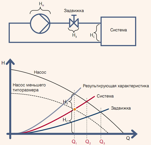
Figure 2 – Throttle control
Bypass regulation. A bypass gate valve is installed parallel to the pump and is used to regulate the pump. Compared to a conventional gate valve installed downstream of the pump, the bypass valve will ensure a certain minimum flow rate Qбп pump, irrespective of the system characteristics. Pump flow rate QН equals the sum of the system flow rate QС and flow through the bypass pipe Qбп. The gate valve on the bypass will provide the maximum allowable pressure in the system Нмакс. Even if the required flow value in the system is zero, the pump will never run on a closed gate valve. As with throttle control, the required value of the system flow QС can be supplied by a smaller pump and without bypass; as a result, the flow rate through the pump will be lower and, consequently, energy consumption will also be reduced.
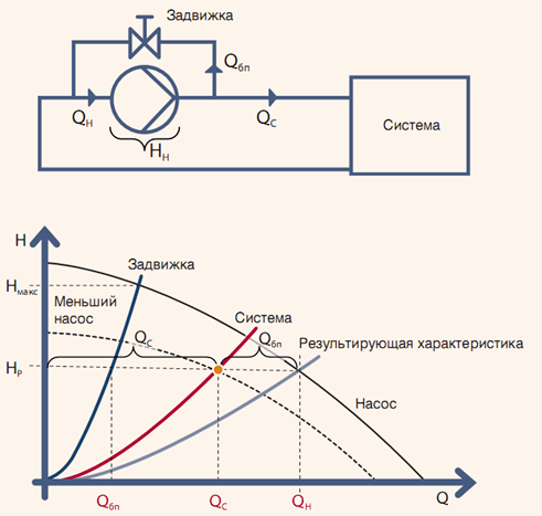
Figure 3 – Bypass regulation
Impeller diameter correction. Another way to adjust the parameters of a centrifugal pump is to correct the impeller diameter: if it is reduced, the performance is reduced. Obviously, reducing the impeller diameter cannot be done while the pump is running. Compared to the throttling and bypass control methods, which can be carried out while the pump is running, the impeller diameter correction must be carried out before installation of the pump or during repair work.
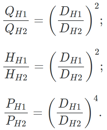
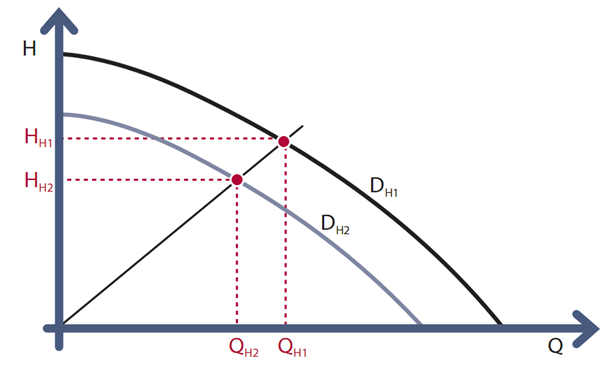
Figure 4 – Impeller diameter correction.
Speed control. Speed control using a frequency converter is without doubt the most effective way to regulate pump performance. Pump flow rateQ is directly proportional to its rotational speed. Pump head Н is directly proportional to the square of the rotational speed, and its power is directly proportional to the cube of the rotational speed. In practice, reducing the speed of the pump leads to a reduction in its efficiency.
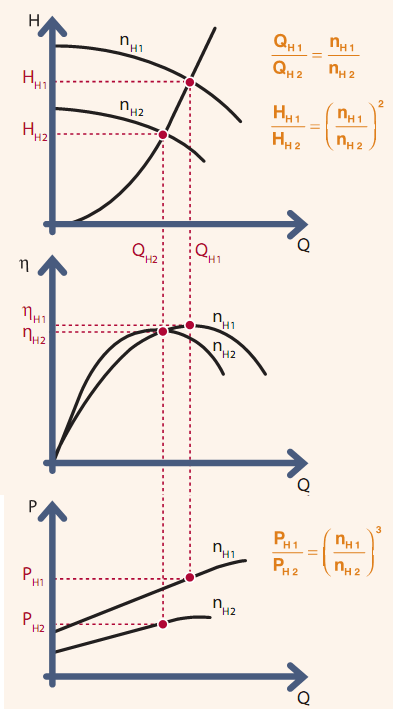
Figure 5 – Rotation speed control.
3.4 Sequential pump operation
Pumps in series (fig. 5) are usually used to increase the head when one pump cannot produce the required head. In this case, the pumps have the same flow and the total head is the sum of the heads of both pumps [8].
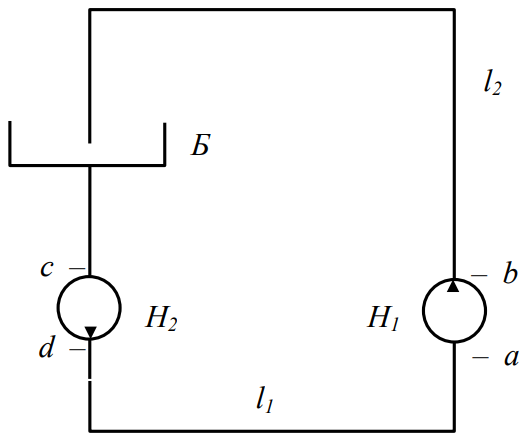
Figure 6 – Diagram of a pumping unit with two pumps in series.
The total characteristic is obtained by adding the ordinates of the energy characteristic of the pumps at the same abscissa (fig. 6). The intersection of the summation with the network characteristic will give the operating point A, which determines the pump delivery rate QA and total head HA two pumps.
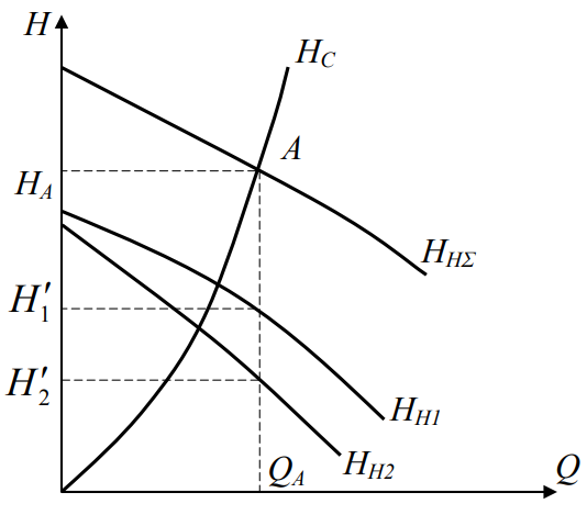
Figure 7 – Energy performance of pumps HH1, HH2, HH∑ and network characteristics HC
By drawing through the point A a vertical straight line, we obtain at its intersection with the energy data of the pumps the head H1' and H2', developed by each of the pumps.
For the closed-loop pumping system shown in fig. 5, sediment is used to compensate for hydraulic losses at the flow rate QA. The pumps can be integrated into the pumping system in various ways.
If they are switched on directly after each other, the total pressure curve of their combined operation is constructed by adding the ordinates of the characteristics of each of the pumps running in series at the same delivery rate. It should be taken into account that the head (pressure) of the second and subsequent pumps increases and the strength of the centrifugal pump housing of the second and subsequent levels may not be able to withstand the overpressure for a long period of time. In addition, hydraulic shut-off valves are subjected to hydraulic shocks and therefore also require increased strength. The piping that connects the pumps in series circuits must not have steep turns and many connections.
To avoid the negative factors listed above, you need to pump H1 move away from the pump H2 for that distance l1, The most efficient is the use of multistage centrifugal pumps, which are characterised by having several impellers on the same axis. The most efficient use is for multistage centrifugal pumps, which are characterised by the fact that they have several impellers arranged on one axis. The result is a step change in head and a single casing which is sturdy enough to withstand a multiple head increase. In addition, the use of multistage pumps is very advantageous as the hydraulic losses are minimal.
When the pumps are connected in series, as previously mentioned, the flow rate remains the same and the total head is equal to the sum of the heads of both pumps taken at the same flow rate. Consequently, the total energy characteristic of the pumps (the curve 3 in fig. 7) is obtained by adding the ordinates of the head curves 1 и 2 both pumps.
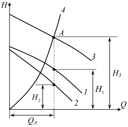
Figure 8 – Energy characteristic of pumps running in series
Intersection of total pump characteristic curve 3 with a network feature4 gives the operating point А.
The abscissa and ordinate of this point give the feed rate respectively QА and total head Н3, which is calculated according to the formula:
where: Н1 and Н2 – the heads produced by the first and second pumps respectively when feeding QА, m3/sec.
3.5 Parallel operation of pumps
Parallel connection of pumps is used to increase the flow rate. Pumps operating in parallel on the same pipework are usually installed close to each other. If the hydraulic resistance of the common pipe is high, the resistance of the supply and discharge pipes up to the node point Д (fig. 8) can be neglected. Since the suction levels of both pumps are the same and the pressure at the junction point is the same for both pumps, the head H of both pumps is the same. If both pumps are replaced by one pump with a capacity equal to the sum of the capacities of both pumps, taken at the same head, the operation of the pump system will not change. To obtain the energy characteristic of this pump or the combined characteristic of the two pumps, add up the abscissa of the curve points H = f (Q) of both pumps taken at the same ordinate (fig. 9) [8].
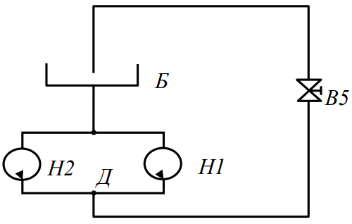
Figure 9 – Schematic diagram of a pump unit with two pumps in parallel
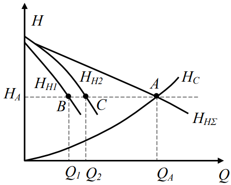
Figure 10 – Energy performance of pumps HH1, H2, HH∑ and network characteristics HC
When two pumps are running in parallel and have the following characteristics 1 and 2 (fig. 10), their cumulative characteristics 3 is constructed by adding the abscissa of the two curve points consecutively 1 и 2, corresponding to one head Н.
In other words, add up the head curves 1 and 2 horizontally. Intersection of the total characteristic 3 with the pipeline characteristic 4 gives the operating point А. The ordinate and abscissa of this point give, respectively, the head НА and total supply QА, which is equal to:
где: где Q1 и Q2 – the flow rates produced by the first and second pumps respectively at the head HА, m.
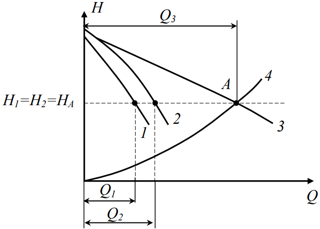
Figure 11 – Energy characteristic of pumps running in parallel.
Conclusions
If high heads are required in steep pipelines, the pumps should be connected in series. In case of steep pipelines the pumps in series are not efficient, in this case a parallel operation of two pumps would be more suitable. Connecting pumps in series is usually less economical than using one pump with the required head.
At the time of writing this abstract, the Master's thesis has not yet been completed. The approximate date of completion of the Master's thesis is June 2021. Full text of the work and materials on the topic can be obtained from the author or his supervisor after this date.
List of sources
- Березин С. Е. Насосные станции с погружными насосами: расчет и конструирование / С. Е. Березин. – М.: Стройиздат, 2008.
- Карелин В. Я. Насосы и насосные станции / В. Я. Карелин, А. В. Минаев. – М.: Стройиздат, 1986. – 320 с.
- Карттунен Э. Водоснабжение II: пер. с финского / Э. Карттунен; Ассоциация инженеров-строителей Финляндии RIL г.у. – СПб.: Новый журнал, 2005. – 688 с.
- Кинебас А. К Оптимизация подачи воды в зоне влияния Урицкой насосной станции Санкт-Петербурга / А. К. Кинебас, М. Н. Ипатко, Ю. В. Руксин и др. // ВСТ. – 2009. – № 10, ч. 2. – с. 12 – 16.
- Красильников А. Автоматизированные насосные установки с каскадно-частотным управлением в системах водоснабжения [Электронный ресурс] / А. Красильникова / Строительная инженерия. – Электрон, дан. – [М.], 2006. – № 2. – Режим доступа: https://promenergo.spb.ru/....
- Лезнов Б. С Энергосбережения и регулируемый привод в насосных и воздуходувных установках / Б. С. Лезнов. – М.: Энергоатомиздат, 2006. – 360 с.
- Николаев В. Потенциал энергосбережения при переменной нагрузке лопастных нагнетателей / В. Николаев // Сантехника. 2007. – № 6. – с. 6873; 2008. – № 1. – с. 72 – 79.
- Промышленное насосное оборудование. – М.: ООО
Грундфос
, 2006. – 176 с. - Штейнмиллер О. А. Оптимизация насосных станций систем водоснабжения на уровне районных, квартальных и внутридомовых сетей: автореф. дис. канд. техн. наук / О. А. Штейнмиллер. – СПб.: ГАСУ, 2010. – 22 с.