
Abstract
Content
- Introduction
- 1. Long-distance AC power transmission features
- 1.1 Long-distance power transmission schemes
- 1.2 Advantages and disadvantages of long-distance power transmission
- 1.3 Electromagnetic transients influence on the operation of relay protection
- 1.4 Research objectives and their implementation methods
- References
Introduction
With the length of the power transmission line over 300 km, its representation in the form of a four-port network with lumped parameters can lead not only to a large calculation error, but even to qualitatively incorrect conclusions. Therefore, the analysis and calculations of the modes of distant power lines should be carried out taking into account the distribution of parameters along the line.
The mathematical model of an electrical system containing long-distance transmissions turns out to be quite complex. And although the methods for studying systems with distributed parameters are sufficiently developed, in relation to even typical power transmission schemes, they are used with a number of assumptions. Studies of short-circuit modes in extended transmission lines are necessary to improve existing and develop new methods for determining fault locations on long lines.
In this regard, it is relevant to develop virtual models of sections of the electric power system with long-distance high-voltage power transmissions in modern software packages.
1 Long-distance AC power transmission features
Long AC lines used to transmit electricity over long distances have their own characteristics. Due to their large length, one has to reckon with the presence of distributed parameters.
There are lines with distributed and lumped parameters. If the line length l is much less than the voltage (current) electromagnetic wavelength λ = V · T, then the distribution of parameters along the line is not taken into account. A distributed line or a long line is a line with a length l > 0,05…0,1λ.
For example, for power lines of industrial frequency f = 50 Hz:
| λ = V · T = 3 · 108 m / s · 0,02 s = 6 · 106 m = 6000 км | (1) |
That is, with a length l > 300…600 km the line should be considered as a distributed chain. Representation of power transmission lines in the form of a four-port network with lumped parameters in this case can lead to a significant calculation error [1].
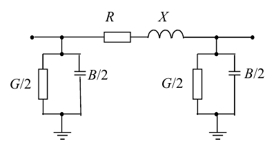
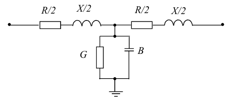
In fig. 1 shows the possible equivalent circuits of a line with lumped parameters [2].
a)
b)
Figure 1 – Equivalent circuits for power lines with lumped parameters
a) U-shaped; b) T-shaped
1.1 Long-distance power transmission schemes
To increase the throughput of a long-distance power transmission line and ensure an acceptable voltage level along its length, various artificial measures are used to improve its parameters [3].
A typical layout for a long line is shown in fig. 2.
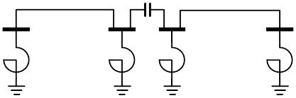
Figure 2 – Long-distance power transmission scheme
Shunt reactors in the diagram in fig. 2 are needed to compensate for excess reactive charging power. Static capacitors connected in series in the line compensate for the inductive resistance up to the reasonable limit of power transmission with a long line [4].
There are three versions of long-distance transmission lines: block, coupled and semi-block [3, 5]. Let's take a closer look at each of them.
- The block version is the simplest and cheapest. However, its application is limited by the requirements for the reliability of power supply to consumers in the receiving system. This requirement is especially important when transmitting large capacities (5–6 тыс. MW), since the line going out of work can significantly affect the operation of the receiving system. When executing the block scheme, it is necessary that the receiving system has a sufficient power reserve, otherwise the shutdown of the unit would lead to the cessation of power supply to a large number of consumers. Therefore, in spite of the simplicity of execution and minimal capital investments during construction, this option is economically unjustified. The block transmission scheme is shown in fig. 3.
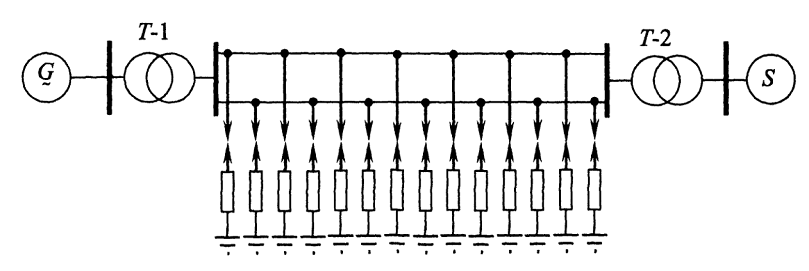
- The associated long-distance transmission option involves the parallel connection of circuits at the transmitting end and at intermediate points. With this option, the line is divided by switching points into a number of successive sections of relatively short length. The transmission scheme with the associated option is shown in fig. 4.
- In the semi-block version of long-distance transmission, the power plant generators transmit power to the receiving system through a double-circuit overhead line. This option is of interest for calculating transient short-circuit processes near the receiving system or transmitting station, since in this case the length of one short-circuit arm is close to the wavelength. The transmission scheme with a semi-block version is shown in fig. 5.
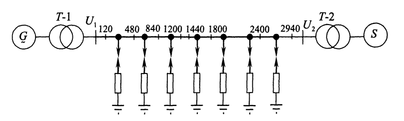
Figure 3 – Block version of long-distance power transmission
It is possible to expand the use of the block version in the event that asymmetric modes with one phase disconnection are provided as operating modes. Since, according to statistics, the vast majority of short circuits are single-phase, this option is advisable. In the event of a single phase outage, up to 2/3 of the normal operating power can be maintained [5]. However, in this case, it is necessary to pay special attention to the issues of maintaining the stability of parallel work..
When the power transmission line is divided into 8 sections in a connected version, in the post-emergency mode caused by the disconnection of one of the sections, power transmission is provided up to 80% of the maximum operating power [3].
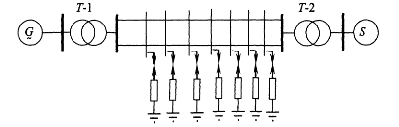
Figure 4 – Associated version of long-distance power transmission
Difficulties in using the linked version are caused by the unfavorable voltage mode when the sections are disconnected, the possibility of self-excitation, the complexity of the dynamic transition, and also the increased level of short-circuit currents compared to the block version.
Figureк 5 – Semi-block version of long-distance power transmission
All three schemes contain special arresters required for overvoltage protection. Dischargers are a spark gap and an active resistance connected in series with it. When the voltage at the point of connection of the spark gap reaches the critical voltage, a spark gap breaks down and a subsequent discharge through an active resistance. The critical voltage is taken 1.8 times the amplitude value of the phase voltage. In the block and semi-block circuits, the arresters are switched on at seven points of the line equidistant from each other, in a connected version – at each switching point. Currently, surge arresters (SA) are widely used instead of arresters. An arrester is a non-linear resistance: as the voltage increases, the resistance decreases, which leads to a discharge through it, thus, the arrester protects expensive equipment [6].
1.2 Advantages and disadvantages of long-distance power transmission
The main advantages of long lines are:
Such lines are designed at high and ultra-high voltages, which allows to reduce power and electricity losses during transmission.
An increase in the wire cross-section leads to a decrease in active resistance, which also helps to reduce power and electricity losses.
Long-distance power transmissions are used to combine power systems for parallel operation. The interconnected power system has a number of advantages over isolated power systems: the possibility of mutual redundancy increases, and the total costs of generating and transmitting electricity are reduced. In the interconnected power system, the total installed capacity turns out to be much less than the sum of the maximum electricity consumption in individual power systems [7].
The use of long-distance power transmissions is also necessary due to the fact that deposits of cheap types of fuel and the location of hydropower resources, as a rule, are significantly removed from industrial centers and large consumers of electricity, and the transmission of electricity is economically more profitable than transportation of fuel by rail and pipelines [8].
At the same time, long lines have their disadvantages, the main of which are:
Economical transmission of energy through such lines is possible only at voltages of 330 kV and above. Due to high voltages and significant capacitive conductivity (due also to the long length), significant charging power is generated.
This can be seen from the formula for calculating the charging power [7]:
| Qзар = U2 · B0 · l | (2) |
где U – nominal line voltage;
В0 – specific capacitive conductivity;
l – line length.
To absorb the excess charging power of the line, shunt reactors are used, which are switched on at substations parallel to the line (lateral compensation). In the absence of compensation, dangerous overvoltages may appear, especially at low loads and at idle. The voltage in the network may exceed the voltage for which the equipment insulation is designed. A mode may occur when the voltage at the beginning of the transmission line will be less than the voltage at the end. The power generated by the power transmission line capacities is directed towards the generators and will have a magnetizing effect on their magnetic system. As a result, the voltage on the generator buses and in the network that is powered by these buses will increase [2, 7].
With an increase in the cross-section, the inductive resistance decreases significantly less than the active resistance. Therefore, in long high voltage lines, where wires of large cross-sections are used, the inductive resistance is much higher than the active.
To reduce the inductive resistance, static compensators are connected in series in the line (longitudinal compensation) [9].
This phenomenon can occur with significant longitudinal compensation. For example, in the absence of damper windings or circuits, it occurs when the reactance of the compensating capacitance Xc is within [10, 11]:
| Х′dΣ < Хс < ХdΣ | (3) |
где Х′dΣ – total transient inductive reactance of the transmission system;
ХdΣ – its total synchronous inductive reactance.
To reduce corona losses, the phase wire is split into several (2–7) parallel wires [12]. Splitting also decreases the inductive resistance, but only slightly. Therefore, to significantly change it, it is necessary to apply longitudinal compensation by static capacitors.
The environmental factor is also important. Long lines are designed for voltages of 330 kV and above, and with an increase in voltage, the dimensions of the supports, the width of the glades, and the area of agricultural land alienation increase. The presence of a corona discharge makes high voltage lines a powerful source of radio and television interference, and the noise of wires increases. You can also note the adverse effects of strong electric fields on humans and animals [13].
1.3 Electromagnetic transients influence on the operation of relay protection
Transients in long lines have a significant impact on the operation of relay protection devices, primarily due to the duration of the attenuation of transients. According to the conditions for ensuring the reliable operation of networks with a voltage of 500 kV and above, it is necessary that the operating time of the starting elements of the main protection of power lines does not go beyond 0,04 s [14, 15]. In lines with a length of 1000 km and more, the decay time of electromagnetic transient processes is 0,1…0,5 s, therefore, the protectors have to work in a transient process.
In fig. 6, as an example, the results of [3] calculation of a short circuit for a block version of a distant transmission line are given.
a)
b)
Figure 6 – Change of a) voltage (animation: 5 frames, 94 kilobytes 7 cycles of repetition) and b) current (animation: 5 frames, 45 kilobytes 7 cycles of repetition) with a three-phase short circuit on a long line
The presence of free periodic high-frequency components in the short-circuit current also complicates the operation of relay protection and automation. The use of special frequency filters allows partially eliminating the influence of free components. But the filters do not completely solve the problem of detuning, since during short circuits in certain places of a long line, periodic free components appear with frequencies close to industrial [16]. This forces to narrow the passband of the filters, which ultimately leads to an increase in the duration of the starting protection elements..
1.4 Research objectives and their implementation methods
The following main tasks of studying electromagnetic transient processes in long lines can be distinguished [17, 18]:
Accuracy requirements may differ depending on the purpose of the calculation. For example, the accuracy in the selection of electrical devices may be low. This is due to the large interval between the characteristics of industrial devices [20]. When calculating for the purposes of relay protection and automation, the accuracy should be quite high. And when calculating in long lines, due to the presence of periodic free components, it is necessary to perform frequency decomposition of the obtained instantaneous values.
Various methods for calculating transients are discussed in more detail in the second part. The complexity of the mathematical apparatus for the study of electromagnetic transient processes in long lines leads to the need to use a computer. The use of special programs for modeling (MATLAB, Power Factory) can significantly simplify the research task, however, in this case, attention should be paid to the specifics of entering the initial data.
References
- Рыжов Ю.П. Дальние электропередачи сверхвысокого напряжения – М.: Издательский дом МЭИ, 2007. – 488 с.
- Идельчик В.И. Электрические системы и сети: Учебник для вузов. – М.: Энергоатомиздат, 1989. – 592 с.
- Куликов Ю. А. Переходные процессы в электроэнергетических системах: учеб. Пособие / Ю.А. Куликов. – Москва: Издательство Омега-Л. - 2013. – 384 с.
- Веников В. А., Рыжов Ю. П. Дальние электропередачи переменного и постоянного тока: Учеб. пособие для вузов. – М.: Энерrоатомиздат, 1985.–272 с.
- Каганов З.Г. Электрические цепи с распределенными параметрами и цепные схемы. – М.: Энергоатомиздат, 1990. – 248 с.
- Кадомская К.П., Лавров Ю.А., Рейхердт А. Перенапряжения в электрических сетях различного назначения и защита от них. – Новосибирск: НГТУ, 2004. – 319 с.
- Лыкин А.В. Электроэнергетические системы и сети: учебник для вузов. – М.: Юрайт, 2018. – 360 с.
- Ананичева С.С., Бартоломей П.И., Мызин А.Л. Передача электроэнергии на дальние расстояния – Екатеринбург: УГТУ-УПИ, 1993.–80 с.
- Зарудский Г.К. Дальние электропередачи в примерах/ Г.К. Зарудский, Е.В. Путятин, Ю.П. Рыжов и др., под ред. Ю.П. Рыжова. – М.: Издательство МЭИ, 1994. – 278 с.
- Эрнст А.Д. Электромеханические переходные процессы в электрических системах: Курс лекций. – Нижневартовск: Изд-во НВГУ, 2013. – 130 с.
- Веников В.А. Переходные электромеханические процессы в электрических системах: учеб. для электроэнергетических вузов. – М.: Высш. шк., 1985. – 536 с.
- Александров Г.Н. Коронный разряд на линиях электропередачи. – Л.: Энергия, 1964. – 228 с.
- Александров Г.Н. Установки сверхвысокого напряжения и охрана окружающей среды. – Л.: Энергоатомиздат, 1989. – 360 с.
- Киреева Э.А., Цырук С.А. Релейная защита и автоматика электроэнергетических систем. – М.: Издательский центр «Академия», 2010. – 288 с.
- Федосеев А.М., Федосеев М.А. Релейная защита электроэнергетических систем: Учеб. Для вузов. – 2-е изд., перераб. и доп. – М.: Энергоатомиздат, 1992. – 528 с.
- Лосев С.Б., Чернин А.Б. Расчет электромагнитных переходных процессов для релейной защиты на линиях большой протяженности. – М.: Энергия, 1972. – 144 с.
- Рожкова Л.Д. Электрооборудование электрических станций и подстанций/ Л.Д. Рожкова, Л.К. Карнеева, Т.В. Чиркова – М.: Издательский центр «Академия», 2007. – 448 с.
- Крючков И.П. Переходные процессы в электроэнергетических системах: учебник для вузов/ И.П. Крючков, В.А. Старшинов, Ю.П. Гусев, М.В. Пираторов, под ред. И.П. Крючкова. – М.: Издательский дом МЭИ, 2008 –416 с.
- Долгинов А.И. Техника высоких напряжений в электроэнергетике. – М.: Энергия, 1968. – 464 с.
- Короткие замыкания и выбор оборудования : учеб. пособие для вузов / И. П. Крючков, В. А. Старшинов, Ю. П. Гусев [и др.] ; под ред. И. П. Крючкова, В. А. Старщинова – М.: Изд. дом МЭИ, 2012. – 568 с.