
Thermal model of the TM-25/10 transformer
Содержание
- 1. Thermal model of the TM-25/10 transformer, its analysis and verification
- 1.1. Thermal modeling
- 1.2. Thermal model check
- 2. Practical execution of transformer overload protection
- 2.1. Development of an algorithm for protection
- 2.2. Permissible overload rate for continuous operation of the transformer with changes in ambient temperatures
- 2.3. Assessment of insulation wear depending on winding temperatures
- List of sources
1. Thermal model of the TM-25/10 transformer, its analysis and verification
1.1. Thermal modeling
Power transformers are the most expensive elements in the power supply system, therefore, with the current significant underloading of transformers, the state bears significant financial costs. The maximum load of transformers at enterprises, defined as the ratio of the half-hour maximum load to the rated power of the transformer, rarely exceeds 60%. This situation, in particular, is due to the fact that thermal processes in oil transformers are not fully understood. And, first of all, because it is technically difficult to measure the temperature of the winding, the wire of which is under high voltage.
The lack of suitable instruments and devices for monitoring and measuring the temperatures of individual parts of transformers has led to the fact that their rated power is selected with an unjustified margin. Thus, it is required to develop an improved methodology for calculating the load capacity of transformers, convenient for engineering calculations and based on the main provisions of IEC and GOST.
Based on the thermal model, the thermal parameters of 10 / 0.4 kV oil transformers can be calculated.
The main factors limiting the load of transformers are the maximum permissible temperatures of their main parts, as well as the thermal wear of their insulation. The main thermal parameters of power transformers include the temperatures of the most heated points (HHT) of the winding, oil and magnetic circuit. Each of these parameters should not exceed a certain critical value.
The process of heat transfer in a transformer is complex, where all three types of heat transfer are manifested: heat conduction, convection, radiation, which is described in detail in [ 5 ], [ 6 ]. The heat transfer coefficients in different parts of the transformer themselves depend on temperature according to a complex law, and the real temperature distribution over the cross section of the transformer is nonlinear and depends on many factors. Therefore, a number of simplifications are introduced to describe thermal processes. In particular, in [ 5 ], [ 6 ] consider a simplified thermal model of a real transformer, consisting of three homogeneous bodies: windings, oil and magnetic circuit, the heat transfer coefficients of which do not depend on temperature.
The thermal equivalent circuit makes it possible to calculate the temperatures of the elements at known power outputs and ambient temperatures. For the compilation and analysis of thermal equivalent circuits, the property of similarity of thermal and electrical processes is used. Assuming that the current is equivalent to the heat flux, and the voltage is equivalent to the temperature, let us reduce the calculation of the thermal regime to the analysis of the electrical circuit, which obeys Ohm's and Kirchhoff's laws. Drawing up a thermal equivalent circuit has a certain complexity. At the initial stage, it requires an analysis of all heat fluxes inside the object under study. For each heat flux, heat sources, thermal resistances and heat capacities of objects on the heat path are determined. The equivalent circuit parameters are found by calculation and are determined by the passport data of the transformer. In the future, we compose an electrical circuit equivalent to a thermal one for a two-winding three-phase power transformer TM-25/10.
Assumptions made when simplifying the thermal equivalent circuit:
- at the initial moment of heating, only the winding is heated, heat transfer to the surrounding insulation and other elements is insignificant;
- in a steady state, all elements of the transformer, except for the primary winding, are heated evenly;
- at the initial moment, the oil temperature is equal to the ambient temperature.
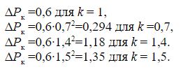
The sources of heat in the transformer are no-load losses ΔРхх and short-circuit losses ΔРкз. In this case, ΔРкз is calculated according to the formula given in [ 5 ]: Δ
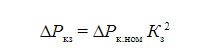
where Kz = S / Snom - the load factor of the transformer; S - load power; Snom - rated power of the transformer; ΔPknom - short circuit losses at rated load.
Heat transfer in a power transformer is as follows. In the process of cooling, the magnetic circuit and the winding give off their heat to the oil by convection, while the oil, in turn, by convection and heat conduction, gives off heat to the walls of the tank, which is cooled by heat conduction and radiation, giving off heat to the cooling medium.
Non-stationary thermal processes in such a model are described by a system of differential equations, which is given in [ 5 ] for the heating process at zero temperature of the cooling medium and zero initial conditions:
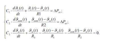
Here indices 1, 2, 3 denote the numbers of thermal bodies: 1 - magnetic circuit; 2 - winding; 3 - oil. Index 0 denotes a cooling medium; Ri - thermal resistances between the corresponding thermal bodies, that is, these are the losses transmitted from one body to another, per 1 ° C of the temperature difference between the bodies (W / ° C); C1, C2, C3 - heat capacity of the corresponding bodies (Wh / ° C); ϑ1, ϑ2, ϑ3 - excess of temperatures of the corresponding bodies over the temperature of the cooling medium (° С); P1, P2, P3 - electrical losses in the corresponding bodies (W).
Instead of the designations for the quantities ϑ1, ϑ2, ϑ3, adopted in [ 5 ], we will use the designations adopted in GOST, that is, instead of ϑ1 - ϑс, instead of 2 - ϑннт, instead ϑ3 - ϑm.
Based on the accepted assumptions, the equivalent circuit is reduced to the form shown in Figure 8.1.
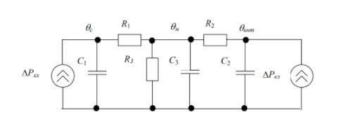
Picture. 8.1 - Thermal equivalent circuit of oil transformer for transient thermal process
Here thermal resistances are represented by resistors, and heat capacities - by capacitors. θс, θннт, θm - respectively, the temperatures of the magnetic circuit, winding and oil. The proposed scheme is universal and allows to obtain curves of both cooling and heating for any period of time, at any load factor of the transformer.
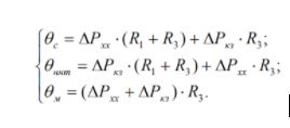
Let us consider a special case when a steady-state thermal regime takes place. For such a case, you can draw up a simplified thermal equivalent circuit obtained from the circuit (Figure 8.1) at a constant temperature. Such a scheme is shown in Figure 8.2. From the diagram (Figure 8.2), you can make a system:
Let us introduce the designations for the excess of the magnetic core temperatures over the oil temperature: ϑsm = θs −θm; windings over the oil temperature: ϑnm = θnnt −θm and the excess of the oil temperature over the temperature of the cooling medium θcool: ϑ m = θm - θcool.
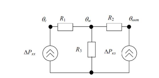
Figure 8.2 - Thermal equivalent circuit of an oil transformer in a steady-state thermal mode
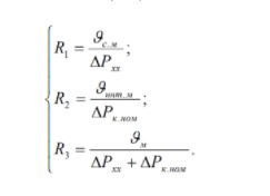
Taking into account the introduced designations and taking Кз = 1, we find R1, R2, R3 from system (8.3):
The resulting equivalent circuit does not imply difficulties for analysis, since it is easily converted according to the laws of TOE or analyzed directly using simulators of electronic circuits, for example, Micro-Cap, Multisim.
The main difficulty is finding the parameters of the equivalent circuit elements. Therefore, the equivalent circuit is simplified and the parameters of the elements are found by experimental and calculation methods. The purpose of the simplification is to reduce the number of elements to such an extent that these elements can be determined experimentally and the accuracy of the calculations will be acceptable.
According to Table 3 in GOST R 52719-2007, the temperature rise of individual elements of the oil transformer over the temperature of the cooling medium (air or water) during heating tests on the main branch should not exceed the following values:
- for windings with natural oil circulation, the temperature rise should not exceed 65 ° C;
- for oil in the upper layers, the temperature rise must be within 60 ° C;
- for the surface of the magnetic system and elements of metal structures - 75 ° C.
In the future, these temperature values will be used to compile a thermal model when calculating the thermal resistances of transformer structural elements.
Based on GOST 11677-85 clause 2.1.3. the maximum allowable temperature of the hottest point of the winding for systematic overloads of transformers of voltage classes 110 kV and below is 140 ° C. The maximum permissible oil temperature in the upper layers is 95 ° C. We take these temperature parameters as limitations on heating the winding and oil in the thermal model.
Changes in oil and winding temperatures will correspond to a two-stage rectangular load curve (Figure 8.3).
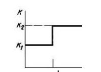
Figure 8.3 - Two-stage rectangular load graph of the transformer
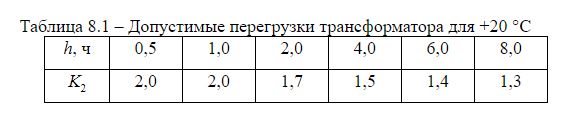
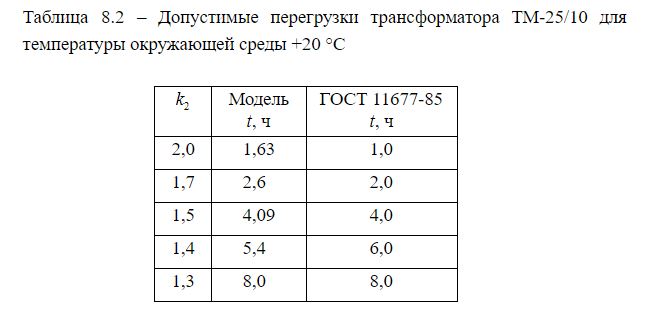
Table 8-14 of GOST 11677-85 shows the values of permissible emergency overloads depending on the value of the initial loads at various values of the temperature of the cooling medium for transformers of voltage classes up to 110 kV inclusive. The table of permissible overloads of K2 oil transformer at an ambient temperature of + 20 ° C for K1 = 0.7 is presented below.
1.2. Thermal model check
To calculate the elements of the equivalent circuit, we will take the passport data of the TM-25/10 power transformer from [ 1 ].
ΔPcnom = 0.6 kW; ΔPхх = 0.13 kW.
Transformer weight (full) - 360 kg
Oil weight - 90 kg.
The mass of the active part is 12.7 ∙ 3 + 3.9 ∙ 3 = 49.8 kg (aluminum), [ 2 ].
The mass of the magnetic circuit is 360-90-49.8 = 220.2 kg.
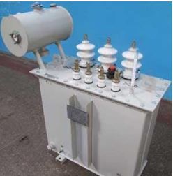
Figure 8.4 - Appearance of the TM-25/10 transformer
Parameters of the TM-25/10 power transformer:
C0oil = 1.964 kJ / (kg K) - for oil at 70 ° C, [ 4 ].C0ref = 0.951 kJ / (kg K) - for aluminum winding at 70 ° C, [ 3 ].
C0magn = 0.426 - for electrical steel at a temperature of 70 ° С, [ 5 ].
Cooling medium temperature - Θcool = 20 ° С.
The power depends on the load factor of the transformer squared, since the heating due to losses in the transformer is determined by the current flowing in the windings, Q = I2Rt, kW, therefore: P = P0kн2.
For instance:
Next, we calculate the thermal resistance Ri and capacitance Ci (heat capacity) for the thermal equivalent circuit:
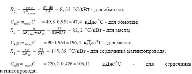
Here, the notation ϑ is used - the temperature difference, respectively, of the magnetic circuit - oil, winding - oil, oil - environment.
To speed up the process in the model, it is recommended to multiply all capacities by 10-3. The thermal equivalent circuit for TM-25 is shown in Figure 8.4.
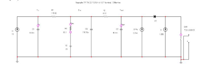
Figure 8.5 - Thermal diagram of ТМ-25, executed in Microcap 9 environment
For an ambient temperature of +20 ° C, the heating time of the oil at k1 = 0.7 and k2 = 1.5 to the permissible temperature of +95 ° C according to GOST will be: 14.74 s ∙ 1000/3600 h = 4.09 h. This value in GOST corresponds to 4.0 hours.
The value of the permissible transformer overload time for each overload factor k2 is summarized in Table 8.2
The error is due to the choice of the values of the specific heat capacities of materials and their mass, and the dimensions and design of transformers from different manufacturers can vary, which can also affect the result, but in general the dependence corresponds to that laid down in GOST.
We will also test our model at different temperatures of the cooling medium: from 0 ° С to +40 ° С for k1 = 0.7 and k2 = 1.4.
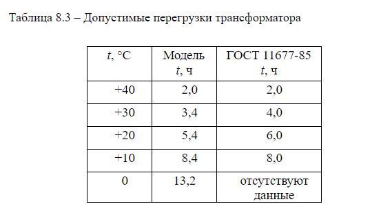
It can be concluded that when the temperature of the cooling medium changes, the model reacts to its change in accordance with GOST, taking into account errors.
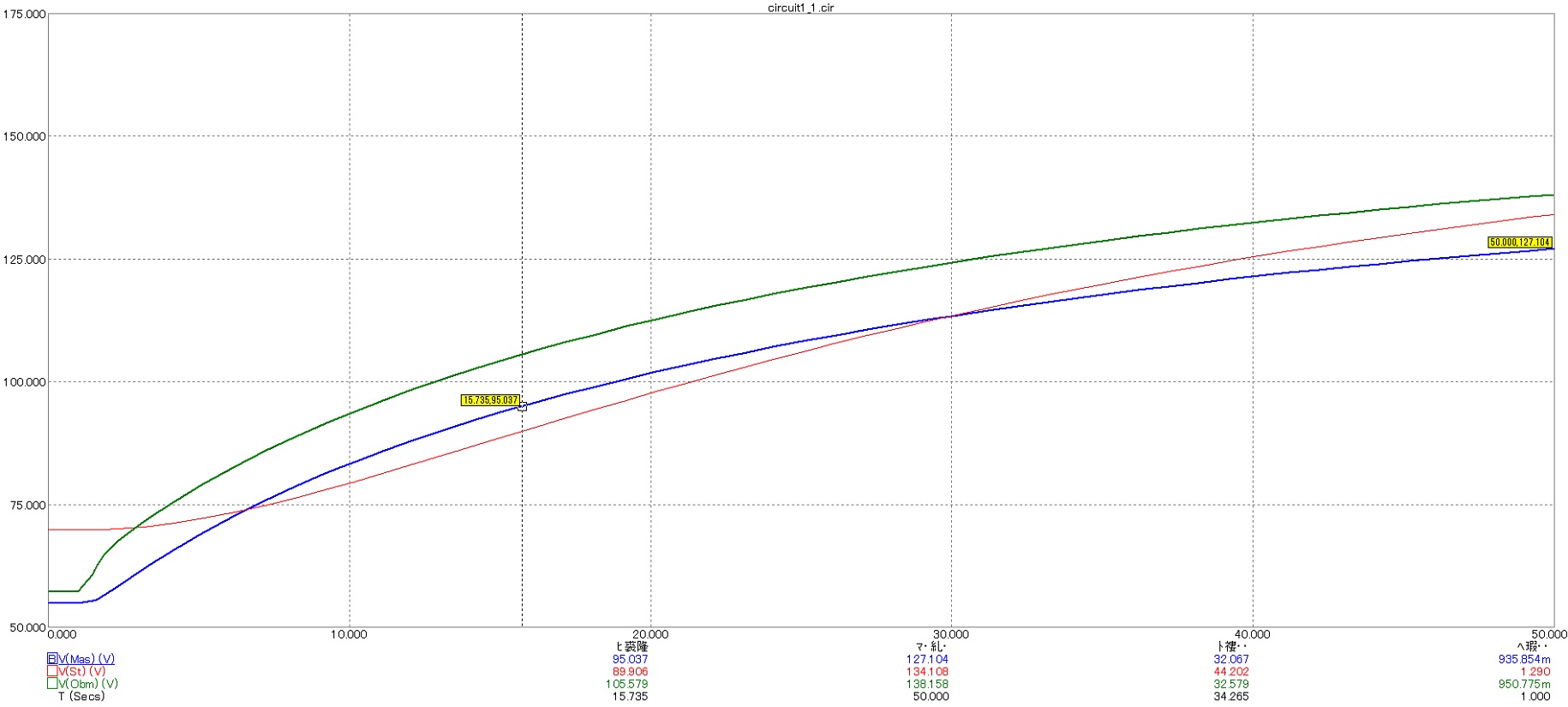
Figure 8.6 - The process of heating parts of the TM-25/10 / 0.4 transformer during overload
2 Practical execution of transformer overload protection
2.1. Development of an algorithm for protection
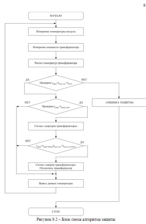
Based on the results obtained by the thermal model of heating of the TM-25/10 transformer, we will draw up an algorithm for the protection operation (Figure 9.1).
Работа защиты состоит из этапов:
- obtaining initial data on ambient temperature, currents or transformer power;
- calculation of temperatures using the transformer model;
- comparison of the obtained temperature values with the setpoints;
- signaling.
In addition, there is a self-diagnostic function that checks the adequacy of the model by comparing the temperature values with each other.
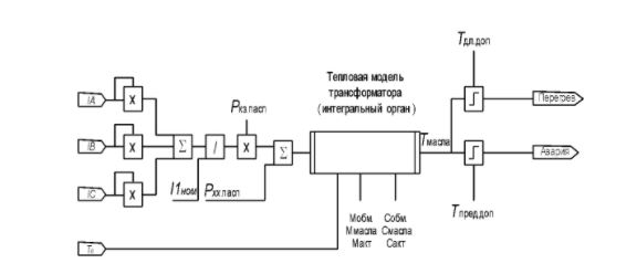
Figure 9.1 - Algorithm of protection work
2.2. Permissible overload rate for continuous operation of the transformer with changes in ambient temperatures
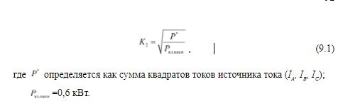
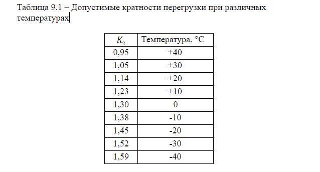
According to the model (Figure 8.1), we determine the permissible overload of the transformer, provided that the oil temperature in the transformer tank does not heat up above 95 ° C. The load factor of the transformer in the initial mode is assumed to be K1 = 0.7. Let us omit the transient processes occurring in the transformer and set the steady state in the thermal model (the key is open). The data calculated in the thermal model are summarized in Table 9.1. The overload factor is defined as:
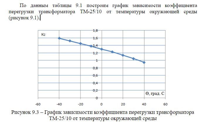
To assess the protection capabilities, let us compare the overloads obtained in the model with the normal permissible - K2 = 0.7. To do this, we will take the following distribution of average temperatures for the year: winter -10 ° C, spring +10 ° C, summer +20 ° C, autumn 10 ° C. Let each season last 3 months.
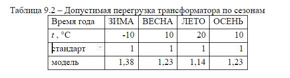
For a transformer with a rated power of 25 kVA, we get:
∆P = 25 ∙ (0.38 ∙ 91 + 0.23 ∙ 91 + 0.14 ∙ 91 + 0.23 ∙ 92) = 2235.25 (kW), where ∆P is the power of possible underloading of the transformer per year.
That is, the protection of the transformer based on the thermal model allows you to keep the load while reducing damage and under-supply of electricity.
2.3. Assessment of insulation wear depending on winding temperatures
Having systematized data on the temperature of the transformer windings during the day, month or year, it is possible to estimate the insulation wear according to the method described in GOST 14209-85 p. 2. For turn insulation of heat resistance class A, the base conditionally constant temperature of the most heated point of the winding, at which the speed of the calculated the wear of the coil insulation corresponds to the service life of the transformer is assumed to be 98 ° C.
The aging rate of the insulation depends mainly on the temperature of the hottest point in the winding. Ideally, with a constant load and nominal operating mode of the transformer, when the temperature of the hottest point is equal to the nominal value Θnt.nom, the relative wear of the insulation is taken as unity. If the temperature Θннт increases (decreases) by a certain interval ΔΘ, then the relative wear increases (decreases) by half. For transformers that meet the requirements of GOST 11677, Θnt.nom = 98, C, ΔΘ = 6 ° C.
The relative wear of insulation for the load curve K (t) for a period of total duration T = Δt1 ... + Δti ... + Δtm is:
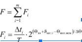
where Fi is the relative wear over the time interval Δti; Θv.e - equivalent ambient temperature; ϑnt.i - temperature rise of the hottest point of the winding: ϑnt i = ϑm i + ϑntm i.
To strictly account for changes in air temperature during the period T, set its average values in each interval Δti. It is allowed to use the equivalent temperature Θv.e of the environment - a conditionally constant value at which the wear of the insulation in the considered period of time will be the same as at changing temperature.
The equivalent temperature of the cooling medium is used only when determining the thermal deterioration of the insulation. To calculate the maximum temperatures in the transformer, which are compared with the permissible values (see Section 8), the highest air temperature for the period under consideration must be set. As such a temperature, GOST 14209–97 recommends the average value of monthly maximums based on the results of long-term observations.
Load curves at which F ≤ 1, while the loads do not exceed the permissible values for the systematic load mode, refer to the diagrams of permissible systematic loads. Load curves at which F> 1, while the loads do not exceed the permissible values for the emergency overload mode, refer to the curves of permissible emergency overloads.
List of sources
- Y.A. Runov, O.G. Shirokov, D.I. Zalizny, D.M. Elk
Energy. News of higher educational institutions and energy associations of the CIS
, Energetika magazine. 2018.01.31. - D.I. Zalizny, O.G. Shirokov
Calculation of the temperature of the main elements of a power oil transformer based on an analysis of the surface temperature of its tank
Energetika magazine. 2012 - O.G. Shirokov, D.I. Zalizny
Thermal equivalent circuits for electric power devices
, Science-intensive technologies, 2008 - D.I. Zaliznyi
Adaptive modeling of thermal processes of electric power equipment in real time
- Komnatny D. "V. Prospects for the use of high-voltage high-frequency transformers in the power industry and in test centers" DV Komnatny, DI Zalizny // Inventor. - 2019. - No. 4. - P. 36-40.