
Abstract
Content
- Introduction
- 1. General information
- 2. Development of computer model of thermal power plant
- 3. Modeling start-up and self-start-up conditions for electric motors of system auxiliaries
- Conclusion
- References
Introduction
The increase in electricity consumption and the complexity of power supply systems require constant improvement of power plants. There is a tendency to create automated control systems based on the use of digital universal and specialized computers. Design automation takes a special place among information technologies.
First, design automation is a synthetic discipline, and many other modern information technologies are its constituent parts.
Secondly, knowledge of the basics of design automation and the ability to work with CAD tools is required for almost any engineer. Enterprises that develop without CAD or with only a small degree of their use turn out to be uncompetitive both because of the large material and time costs for design, and because of the low quality of projects.
Increasing the labor productivity of developers of new products, shortening the design time, improving the quality of project development are the most important problems, the solution of which determines the level of acceleration of the scientific and technological progress of society. The development of computer-aided design (CAD) systems is based on a solid scientific and technical base. These are modern means of computer technology, new ways of presenting and processing information, the creation of new numerical methods for solving engineering problems and optimization. Computer-aided design systems make it possible, on the basis of the latest achievements of the fundamental sciences, to work out and improve the design methodology, to stimulate the development of the mathematical theory of designing complex systems and objects.
1. General information
Self-starting of asynchronous and synchronous electric motors is used for all basic mechanisms of auxiliary needs of power plants of various types. Self-starting of electric motors (EM) for auxiliary needs of thermal power plants is one of the most important operating modes that ensure the continuity of the technological process and stable uninterrupted operation of heat and power equipment during power interruptions and reapplication of voltage to the MV buses, which meets the requirements of regulatory and technical documents. Unsuccessful self-starting of ED SN can lead to emergency shutdown of boilers and turbine generators, which is associated with great economic damage due to insufficient supply of electricity and heat, disconnection of responsible consumers, as well as damage to the main equipment.
The possibility of self-starting ED SN should be provided for at the design stage of a TPP by choosing appropriate power supply schemes and power equipment, relay protection and automation. At block power plants, all the most important mechanisms of their own needs simultaneously ensure the continuity of the technological process of converting the chemical reaction of the fuel into thermal and electrical energy, i.e. normal operation of the power unit, and disruption of any critical mechanism for own needs will lead to disruption of the entire power unit [1]. Hence the high requirements that are imposed on ensuring the continuity of the operation of these mechanisms. The operating personnel of power plants must clearly understand the phenomena occurring in various transient modes of operation of the power unit, one of which is the process of self-starting of auxiliary mechanisms. At the same time, the personnel must have knowledge of both the electrical and thermal engineering parts of the power unit.
2. Development of computer model of thermal power plant
The electrical circuit of Starobeshevskaya TPP was taken as a basis. The computer model of the TPP was created in the CAD program. It consists of a graphic image of the electrical circuit, generated in the graphic editor AutoCAD, and its accompanying information support, located on the sheets of the Excel spreadsheet file [ 2-3 ]. In particular, one of them shows the data of deep-core IM of the auxiliary system. The design scheme is made in a two-layer version. In layer 0, a power output circuit is formed, which includes generator voltage circuits, step-up block transformers, transmission lines for communication with the network substation, as well as working reserve TSNs. Layer 6 forms a circuit with. n., including sections, inputs of operating and backup power, backup power bus, etc. Figure 1 shows the graphical component of the computer model of the electrical part of the power plant. It uses graphic blocks in the form of a point with a number to identify electrical components (shown in red in Fig. 1).
Figure 1 – Diagram of the main electrical connections
During the operation of the power plant, a different number of units can be in operation. Especially often the scheme of a 6 kV auxiliary system is configured in connection with the possibility of supplying its sections with. n. power units from working or standby transformers for their own needs. To form variants of schemes with different composition of equipment in the design scheme, graphic blocks of switches are used. Simulation of their switching on the design diagram is carried out by replacing the graphic blocks of the switched on and off switches. When calculating transient electromechanical processes in the system of auxiliary needs (starts and self-starts of AM), in order to increase the speed of calculations, the equivalent of the entire scheme of power output in relation to one of the working or standby TSN was applied. To determine this TSN, the circuit is programmatically analyzed, starting from the sections selected by the user with. n., included their inputs and further according to the scheme to TSN. In addition, elements that are not involved in the calculations are excluded from the design scheme of the auxiliary system. For this, an auxiliary test mode of power supply to the load of sections is simulated. n. from the selected TSN and then the elements, the currents of which have zero values, are excluded from the circuit. Determination of voltages at the nodes of the circuit (see Fig. 1) when calculating transient processes is performed by the method of nodal potentials in the vector-matrix form of recording. Calculation of the rotational speeds of the units p. n. in the starting and self-starting modes, it is performed by solving the basic equation of motion of their rotors.
3. Modeling start-up and self-start-up conditions for electric motors of system auxiliaries
On the basis of the ES computer model, numerous calculations of the modes of starting and self-starting of the IM were performed. At the power plant, in order to increase the reliability of the power supply circuit of the dredging pumping station of the second lift, it is planned to change its main power supply circuit from the sections with. n. one of the power units. To substantiate the indicated design solution, multi-variant calculations of the modes of starting and self-starting of the electric motor were performed. As an example, Figure 6 below shows the results of calculating the self-starting mode of the HELL of section 8A of unit No. 1 after a break in their power supply lasting 2.5 seconds. It shows the curves of changes in rotation frequency and voltage changes in the process of self-starting of the IM.
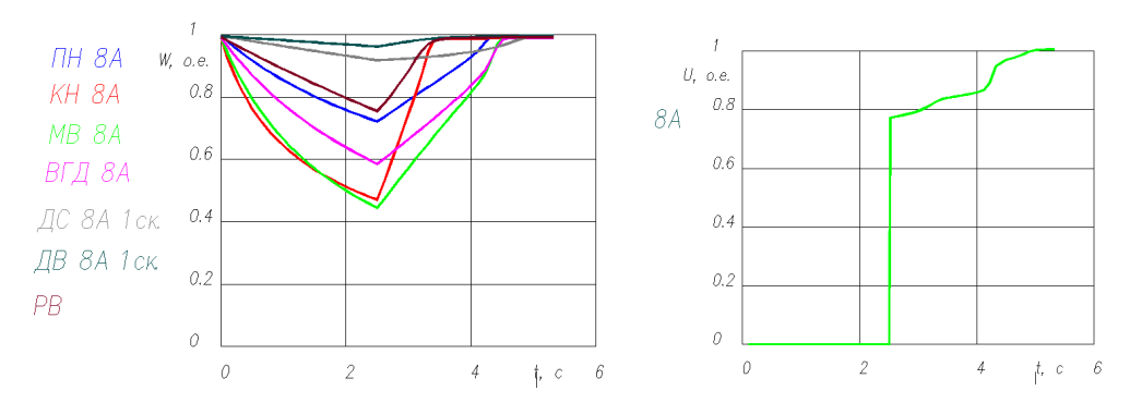
Figure 2 – Changing the frequency of rotation of AM and the voltage on the section in the process of self-start-up
Conclusion
The master's work is devoted to the urgent scientific task of studying the modes of starting and self-starting of electric motors in a 6 kV auxiliary system at a thermal power plant with 200 MW units, based on el. schemes for SbTPP.
- A computer model of the electrical part of one of the power plants of Donbass (Starobeshevskaya TPP) has been developed. With its help, calculations of short-circuit currents and verification of the main electrical equipment and conductors were carried out, both in the power distribution circuit and in the auxiliary system with a voltage of 6 kV.
- The simulation of the start-up and self-start modes of the electric motor of the SN system, which made it possible to select the circuit and mode solutions for the proposed reconstruction of the power supply system of the pumping of the second climb of thermal power plant.
References
- Пушков А.Л. Режимы работы электрооборудования электрических станций. - Киров: Изд-во ВятГУ, 2003. - 93 с.
- Справочник по электроснабжению и электрооборудованию: в 2 т. Под общ. ред. А. А. Федорова. Т 2 Электрооборудование. - М.: Энергоатомиздат, 1987. – 592 с.
- Павлюков, В. А. Разработка САПР электрической части станций и подстанций для учебного процесса / В. А. Павлюков, С. Н. Ткаченко, А. В. Коваленко // Завалишинские чтения'2018, ГУАП, г. Санкт-Петербург, 2018/4–145-153 с.
- Курбангалиев У.К. Самозапуск двигателей собственных нужд электростанций. – М.: НТФ «Энергопрогресск», 2001. - 64 с.
- Павлюков, В. А. Совершенствование методов идентификации параметров эквивалентных схем замещения глубокопазных асинхронных двигателей / В. А. Павлюков, С. Н. Ткаченко. – Электричество, 2018. – №10. – С.54-60.
- Сивокобыленко В. Ф. Параметры и схемы замещения асинхронных двигателей с вытеснением тока в роторе /В. Ф. Сивокобыленко, В. А. Павлюков. – Электрические станции, 1976. - №2.
- Павлюков, В. А. Совершенствование методики обработки данных асинхронных электродвигателей в учебной САПР / В. А. Павлюков, В. С. Рудов // Инновационные перспективы Донбасса: материалы III Международной научно-практической конференции. Секция Перспективы развития электротехнических, электромеханических и энергосберегающих систем, 24 мая 2017 г., г. Донецк. Т. 2. – Донецк: ДонНТУ, 2017. – С. 35-39.
- Георгиади В.Х. Поведение энергоблоков ТЭС при перерывах электроснабжения собственных нужд. Часть 1. – Москва, НТФ «Энергопрогресс», 2003. [Библиотечка электротехника, приложение к журналу «Энергетик»; выпуск 52].
- Георгиади В.Х. Поведение энергоблоков ТЭС при перерывах электроснабжения собственных нужд. Часть 2. – Москва, НТФ «Энергопрогресс», 2003. [Библиотечка электротехника, приложение к журналу «Энергетик»; выпуск 53].
- Георгиади В.Х. Поведение энергоблоков ТЭС при перерывах электроснабжения собственных нужд. Часть 2. – Москва, НТФ «Энергопрогресс», 2003. [Библиотечка электротехника, приложение к журналу «Энергетик»; выпуск 54].