
Content
- Introduction
- 1. Relevance of the topic
- 2. Goal and tasks of the research
- 3. Description of inclined bridge design skip hoist
- 4.Characteristic defects and damage to steel structures
- 5. Analysis of the stress-strain state of an inclined bridge
- 6. Determination of natural frequencies and vibration patterns of structures
- 6.1 Determination of natural vibration frequencies by finite element method
- 6.2 Performing modal analysis at ANSYS
- 6.2.1 Geometric bridge model
- 6.2.2 Performing modal analysis in the ANSYS package
- Conclusion
- References
Introduction
Some blast furnaces are supplied with charge materials using a skip hoist. This device consists of: an inclined bridge, skip, rope, deflecting blocks and a skip winch as a drive. The skip winch is located in the blast furnace's engine room and operates continuously for short periods of time.
The reliable operation of the skip hoist is one of the factors determining the continuous flow of the cast iron production process. Among the many parameters ensuring the trouble-free operation of a skip hoist is the quality of its maintenance and repair, which is largely determined by the level of personnel training and the degree of development of normative technical documentation. The long service life of the skip hoist leads to the appearance and development of faults, the elimination of which requires a prolonged blast furnace shutdown.
At present, the main area of improving the quality of service ensuring the failure-free operation of the skip hoist is the development of inspection maps and assessment of the risks of failure of structural elements.
Versatile information on the stress-strain state of the skip hoist's steel structures and understanding the factors that cause it will largely contribute to the effective solution of these problems.
1. Relevance of the topic
The blast furnace requires an uninterrupted supply of charge materials to the feeder. The charge material feeders are subject to stringent requirements and a delay in loading even for a short period of time leads to the kiln being moved to a quiet or complete shutdown. These machines must therefore have high productivity, increased operational reliability and the ability to fully automate the furnace loading process.
One of the main ways to feed charge materials into the blast furnace is by means of a skip hoist, where charge materials are delivered to the grate and loaded into the receiving hopper of the backfill machine. This device consists of: an inclined bridge, skip, rope, deflecting blocks and a skip winch as a drive [1].
During the work of the hoist, the metal structure of the bridge is affected by dynamic loads, which cause oscillations. Studying the strength of the hoist's inclined bridge and studying the stresses and deformations caused by vibrations is an important task.
During the work of the hoist, the metal structure of the bridge is affected by dynamic loads, which cause oscillations. Studying the strength of the hoist's inclined bridge and studying the stresses and deformations caused by vibrations is an important task.
Analysis of literature sources [2] has shown that skip hoist failures form the third largest group of accidents (after furnace and air tuyeres steel structures), which accounts for about 13% of all failures and 8.5% of total downtime. The share of failures of the inclined bridge is relatively small, but the elimination of its consequences causes significant losses (Figure 1).
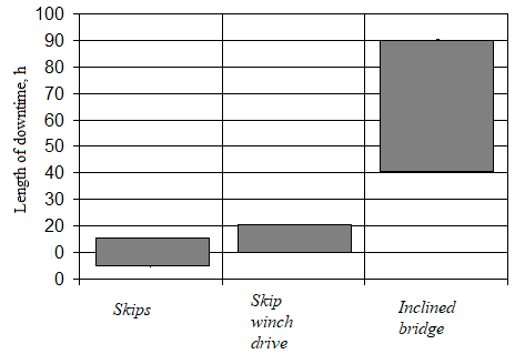
Figure 1 - Ratio of time spent on restoring the performance of a skip hoist, depending on where the accident occurred
It is this element of the skip hoist's design that must be characterised by a high level of reliability, as it has no redundancy, is under constant load and the loads vary over a wide range and are variable, its repair requires considerable time and manpower, and individual sections are at an altitude. The issues related to ensuring that the tilting bridge is operational are therefore relevant. In order to develop maintenance measures and select diagnostic parameters for the assessment of the technical condition of a sloping bridge, information is needed on possible defects in metal structures and the regularities of their development. Such information can be obtained by mathematical modelling of the stress-strain state of an inclined bridge using the finite element method.
2. Goal and tasks of the research
The purpose of my work is to investigate the stress-strain condition of the skip bridge of the blast furnace hoist. The following tasks are set to achieve the objective:
- To analyse the design of the skip hoist inclined bridge.
- To perform an analysis of the types and causes of faults in the inclined bridge steel structure.
- Develop geometric two- and three-dimensional inclined bridge models.
- Identify the forces acting on the inclined bridge metalwork when skip moving and assess the stresses they cause.
- Perform a vibration analysis of the metal structure (determine the natural and forced oscillation frequencies).
3. Description of inclined bridge design skip hoist
There are two types of skip hoist inclined bridges: with lattice trusses and with solid beams.
Currently, all blast furnace bridges are welded as they are more economical than rivets.
Beam bridges are less prone to mechanical vibrations. But since they are considerably heavier than latticework, all new furnaces are equipped with latticework welded bridges.
The bridge is placed on two supports, one of which is located at the bottom of the skip hole wall and the other on a pylon. The upper part of the bridge is a cantilever. The bridge has platforms and supports for skip rope blocks and cone ropes, as well as a rotary crane to repair the blocks. The angle of inclination of the bridges is taken to be 47–54°; the angle of inclination of the track in the skip pit is 58–61°.
The flat support column is sufficiently flexible and therefore allows for longitudinal deformation of the bridge.
The inclined bridge is a spatial metal structure consisting of two side vertical trusses connected to each other by cross ties.
The truss consists of a lower and upper belt, posts and struts. All these elements are made of corners.
The side trusses in the lower belt are connected by a channel, in the upper belt by corners and ties made of strips.
Part of the skip bridge consists of cross beams connected to the lower belts of the vertical trusses. The cross beams are covered with I-beams, on which the rails are fastened. Counter-rails are installed to prevent the skip from leaving the track. The lower part of the bridge is lined with steel sheeting to protect it from materials that could fall out of the skip.
The upper support column (pylon) is made flat as a lattice truss. The material for the elements of the inclined bridge is steel grade Art.3 [3].
Figures 3.1 (a, b) and 3.2 (a, b) show the different design options for the inclined bridge.
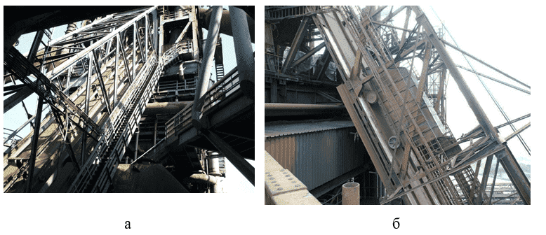
Figure 3.1 - Inclined bridge with grate farm
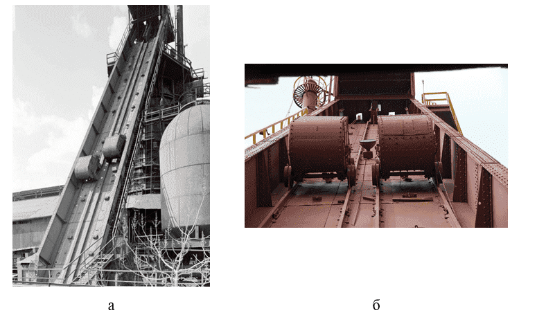
Figure 3.2 - Inclined bridge with solid beams
The above damage may manifest itself in inclined bridge metal structures, but to identify them more accurately, modelling – mathematical and physical – should be used, as the main causes contributing to the development of damage and reducing the reliability and durability of bridge metal structures are the intensity of loading, operating conditions and long life.
4.Characteristic defects and damage to steel structures
According to [4], the most typical defects and damages to metal structures of various equipment and structures are:
- weakening of the cross-section;
- deformations of individual elements or structures as a whole in the form of bending, deflections, curvatures;
- deviation or displacement of structures from the design position;
- non-project placement of structural elements;
- cracks in the base metal, in the welded joint and the near-suture area;
- defects in welds: irregularity of welds, welding defects, absence of welds;
- bolt and rivet defects: cracked joints, incomplete heads, core misalignment, loose package, weakened or missing bolts or rivets, etc.;
- the presence of stress concentrators in the structures;
- mutual displacement of structures (misalignment of elements, out-of-node smearing, etc.);
- mechanical or thermal damage to metal;
- destruction of anti-corrosion protective coatings and corrosion damage to metal and compounds;
- illiterate reinforcement of structures;
- deformations in structural elements due to uneven precipitations;
- non-project application of loads on structural elements during operation (suspension of technological equipment, hangers allowed during repair work, etc.).
5. Analysis of the stress-strain state of an inclined bridge
As the steel structure of the inclined bridge is in a complex stress-strain state, the task was first considered in a two-dimensional statement. The bridge design was reduced to a flat single-span cantilever farm with movable A and fixed B supports. BEAM188 type beam elements were used to create the finite element bridge model. The total number of elements was 236. The characteristics of the cross section of the beam elements corresponded to single-shell corner numbers 10, 16 and 20 (GOST 8510-72).
The loads used were concentrated forces arising from the established mode of skip movement along the bridge (Figure 5.1a). In order to find static forces, a typical schedule of skip movement filled with agglomerate was considered, forces in ropes and reactions in skip ropes were determined. The obtained force values were applied along the inclined bridge route. In the course of the simulation, 6 loading options were considered and the location of the force application points is shown in Figure 5.1b. Points 1 to 4 are in the span of the farm, points 5 to 6 are in the cantilever part.
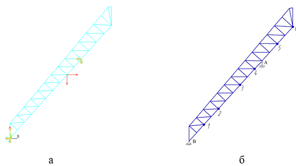
Figure 5.1 - Typical design scheme for inclined bridge (a) and location scheme for force application points (b)
The results of the simulations included deformation patterns (Figure 5.2), longitudinal and transverse force episures, bending moment episures (Figure 5.3) and the distribution of stresses caused by these forces. Table 1 shows the maximum displacements of the bridge structure in the horizontal and vertical directions [7].
Figure 5.2 - Pictures of the deformed state of the inclined bridge
(animation: 7 frames, 5 cycles of repeating, 140 kilobytes)
| Number of the calculation scheme | 1 | 2 | 3 | 4 | 5 | 6 |
| Distance to load application point, m | 8,2 | 16,2 | 28,1 | 36,1 | 48,6 | 57,1 |
| Maximum X-axis offset, mm | 16,2 | 26,4 | 25,6 | 15,7 | 30,6 | 69,4 |
| Maximum span deflection in the Y axis, mm | -10,2 | -17,5 | -17,0 | -9,6 | 4,5 | 13,1 |
| Maximum deflection of the console in the Y axis, mm | 8,4 | 14,9 | 16,9 | 10,8 | -18,6 | -47,0 |
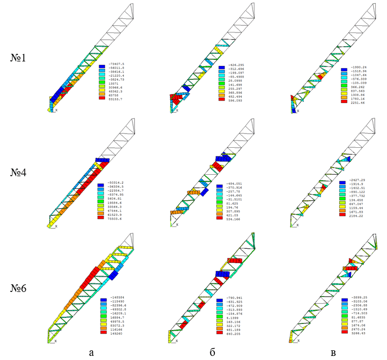
Figure 5.3 - Episodes of longitudinal forces (a), transverse forces (b) and bending moments (c) for design diagrams No. 1, 4, 6
In the next phase of the research, it is planned to simulate the stress-strain state in three dimensions in order to get closer to the real object of research and identify stress concentrations in more detail.
6. Determination of natural frequencies and vibration patterns of structures
One of the components of the strength of the inclined bridge is its stability due to the occurrence and propagation of natural and forced vibrations in metal structures. There are two approaches to the determination of natural frequencies and vibration patterns (modal analysis): the calculated, for example, finite element method (FEM) in the ANSYS software package, and the experimental method – holographic interferometry. Knowing the type of vibration form and the frequency corresponding to it, it is possible to significantly reduce vibration amplitudes, change the natural frequencies by introducing additional structural elements or replacing the material [5].
6.1 Determination of natural vibration frequencies by finite element method
Own (free) vibrations are those that occur in the system in the absence of variables of external influences and are caused by the initial deviation of one of the system parameters from the equilibrium state.
The natural frequency of oscillations of any structure is determined by a formula:
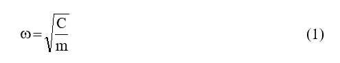
where C – structural rigidity,
m – construction weight.
Modal analysis is performed to determine the frequencies and forms (modes) of natural vibration of structures. Modal analysis can also be the first step for other types of dynamic analysis such as transient, harmonic and spectral analysis.
Modal analysis assumes that the system is linear. All types of nonlinearity – nonlinear material behaviour, contact boundary conditions, final movements – are ignored. Contacts remain open or closed, depending on their initial state.
External forces and damping are assumed to be zero. The equation of free oscillations of the structure in a matrix form is shown:
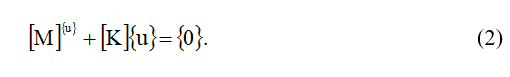
For a linear system, the free oscillations are harmonic and can be recorded in a form:
where{φ}i is the i-th eigenvector, representing the form (module) of oscillations at i-th eigenvector frequency;
ωi – i-th own circular frequency (radian per unit of time);
t – time.
By substituting (3) in (2), we will receive:
For complex structures, the solution of equation (4) is carried out using numerical methods, most often the finite element method (FEM), which is used in modern computer modelling applications when performing strength, thermal and other types of analysis [6].
6.2 Performing modal analysis at ANSYS
Modal analysis in the ANSYS application package [[9,10] is performed in the following sequence:
- Construction of a geometric model of the object under study.
- Setting the mechanical properties of the material.
- Mesh generation from finite elements within the geometric model. 3.
- Definition of boundary conditions.
- Solution of Equation (4).
- Analysis of results.
It should be noted that the ANSYS package includes various modules that can be used to perform modal design analysis. Namely, ANSYS Multiphysics is the main ANSYS software product, which includes the calculation capabilities of all engineering disciplines, and ANSYS Workbench is a single interactive environment that integrates various software products and has a user-friendly interface [8]. In the course of the survey, both of these modules were used to find a solution to the problem.
6.2.1 Geometric bridge model
Working drawings of the Donetsk Metallurgical Plant were used to build a 3D model of the skip hoist's inclined bridge. The construction was performed in the KOMPAS computer-aided design system. The inclined bridge was conditionally divided into 2 trusses 1, track 2, transverse links 3 (Figure 6.1).
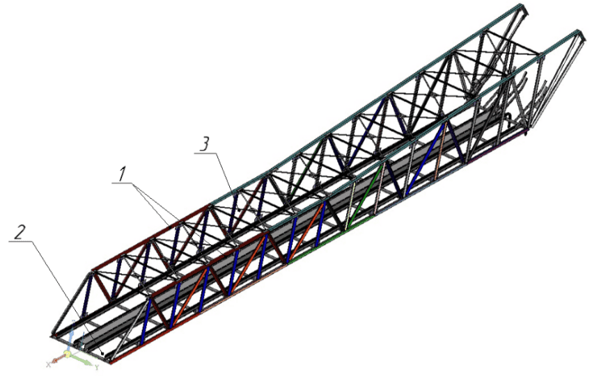
Figure 6.1 - Geometric three-dimensional inclined bridge model
Each farm consists of: lower belt 1, upper belt 2, struts 3, struts 4, overlaps 5 (Figure 6.2).
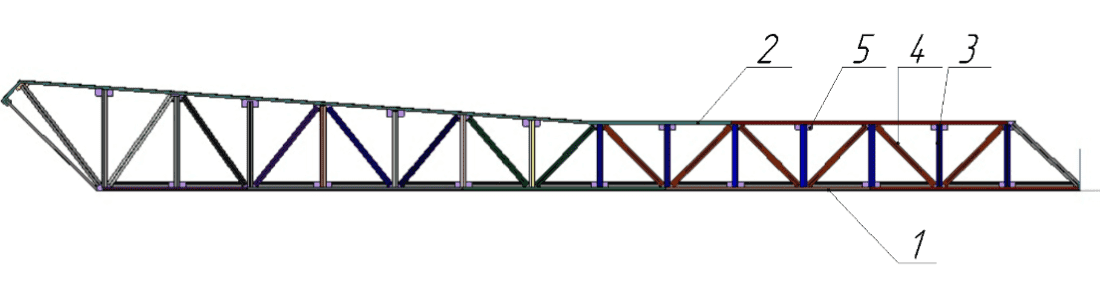
Figure 6.2 - Tilting bridge farm
The lower belt is a double corner No. 16, which is welded to each other using strip linings.
Pillars and struts in the lower and upper part are also welded to the pads. They represent twin corners No. 16. The distance between the props and their length are increased as they move along the inclined bridge route.
The upper belt consists of twin corners No. 16, which are welded to the upper overlays. At the beginning of the route, the corners are placed horizontally and then at an angle of 5 degrees. This component of the model was created using the Kinematic Operation
command.
Farms are connected to each other using channels at the bottom and cross corners and strips at the top. The corners and strips are welded to the upper belt by means of overlaps.
The channels are created on the basis of a sketch using the squeezing operation
command.
The components of the geometric model were joined together by the Distance
and In Place
interface commands. In the latter case, the corresponding part was created directly in the assembly. This technique was used for transverse corners, strips and upper belt lining.
The route is a straight section and an unloading section. In the straight section, the rail is fastened to a I-beam that is attached to a channel.
Unloading curves have been created directly in the assembly using the Cinematic Operation
command. For this purpose, in the middle plane of each rail located in the straight section, a sketch corresponding to the drawing of the upper and lower curvilinear section was drawn, and in the perpendicular plane a sketch containing the contour of the rail cross section was projected.
The discharge curves are connected to the posts by means of brackets, which are rectangular plates. These parts were also created in the assembly by extruding the sketches, which are rectangles.
The total number of components in the inclined bridge model was 386. The weight of the entire object is equal to 70 tonnes, which corresponds to these drawings, i.e. it is possible to consider that the created 3D model adequately represents the real construction.
The model was then imported into the ANSYSWorkbench package.
6.2.2 Performing modal analysis in the ANSYS package
In order to reduce the calculation time, the geometric model of the inclined bridge is designed as a three-dimensional frame structure. For this purpose, in accordance with the drawing, the coordinates of the characteristic points corresponding to the places of welded joints of posts, struts, lower and upper truss belts were initially specified. Next, these points were connected using segments. The view of the frame model is shown in Figure 6.3.
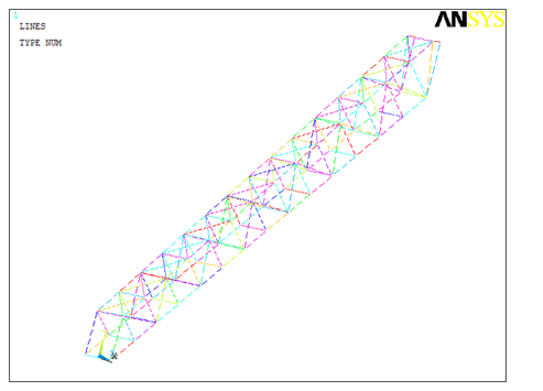
Figure 6.3 - Geometric frame model of inclined bridge
The creation of the finite element model was done by specifying the number of elements on each linear component. The model obtained is shown in Figure 6.4.
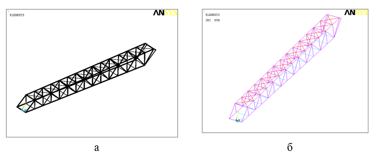
Figure 6.4 - Final element model of inclined bridge: a) showing the cross-sectional shape of the elements; b) with colour display of elements of different shapes
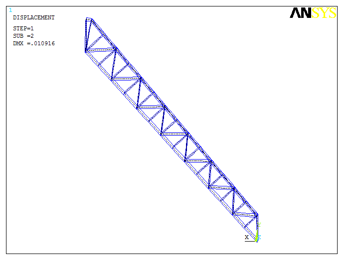
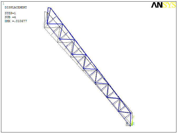
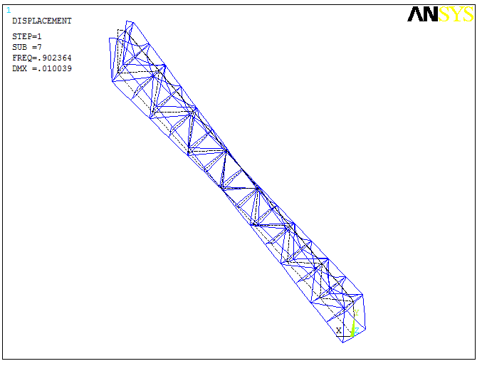
The results of the calculation in the form of vibration forms for the 1st, 4th and 7th natural frequencies are presented in Table 6.1. It should be noted that the obtained frequency values are about 1 Hz, i.e. they are in the low-frequency region.
It can be seen that vibrations at the first eigenfrequency are characterised by an X-axis structure deviation, with the lower part of the bridge in the skip pit moving in a positive direction and the upper part near the furnace column moving in the opposite direction, which will cause tensile-compression stresses in the side trusses.
Oscillations at the fourth natural frequency are characterised by elongation of the structure in the Y axis, which will cause tensile stresses in the side trusses.
Vibrations at the seventh natural frequency are characterised by twisting of the structure at the top and bottom, which will cause torsional stresses in the side trusses.
The results of the calculation show that the natural frequencies of the tilting bridge structure are not high and should not resonate with the frequencies caused by skip movements. For the final conclusion, it is planned to calculate the forced vibrations of the structure.
| 1 | 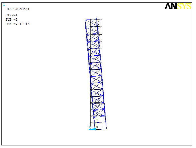 |
 |
| 2 | 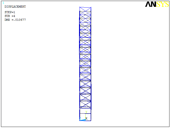 |
 |
| 3 | 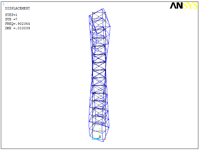 |
 |
Conclusion
A study of the stress-strain state of the steel structures of the blast furnace inclined bridge, carried out using mathematical simulations, showed that the structural elements experience maximum load when a loaded skip is located in the middle of the span and at the extreme point of the farm console. In general, the maximum stresses arising in the longitudinal direction of the bridge elements vary from 46 to 98 MPa and in the transverse direction from 9 to 56 MPa, which does not exceed permissible values. The nature of stresses changes as the skip advances. As the skip moves over the bridge, its upper belt is compressed and its lower belt is stretched. When the skip passes the cantilever part of the bridge, the opposite is true: the upper belt is under tension and the lower belt is under compression.
Although the stresses occurring in the skip bridge elements as a result of static forces do not exceed permissible values, their alternating nature contributes to the nucleation of damage in metal structures.
The main causes of the occurrence and development of damage are dynamic loads causing fluctuations. Therefore, in the second stage, the stability of the inclined bridge was simulated on its three-dimensional model.
The results of the calculation for the spatial structure show that the natural frequencies of the metal structure of the tilted bridge are not high and should not resonate with the frequencies caused by skip movements. For the final conclusion, it is planned to calculate the forced oscillations of the structure.
References
- Целиков, А.И. Машины и агрегаты металлургических заводов.: В 3-х томах. Т. 1. Машины и агрегаты доменных цехов. Учебник для вузов. – М.: Металлургия, 1987. – 440 с.
- Правила технической эксплуатации механического оборудования доменных цехов. – Гос.комитет промышленной политики Украины, 2000. – 323 с.
- Щиренко, Н.С. Механическое оборудование доменных цехов – Учебное пособие. – М.: Металлургиздат, 1962. – 524 с.
- Характерные дефекты и повреждения металлических конструкций
- Сайт Национального Исследовательского Ядерного Университета
МИФИ
- Леонтьев, Н.В. Применение системы ANSYS к решению задач модального и гармонического анализа. Учебно-методический материал по программе повышения квалификации
Информационные системы в математике и механике
. Нижний Новгород, 2006, 101с. - Свичканев, А.И. Моделирование напряженно-деформированного состояния наклонного моста скипового подъемника доменной печи / А.И. Свичканев, Е.В. Ошовская, В.А. Сидоров // Технологические машины и оборудование: материалы XVIІІ Республиканской научно-технической студенческой конференции, 26–28 ноября 2019 г., Донецк – Донецк: ДонНТУ, 2018, 146 с. – c. 93–98.
- Программный пакет ANSYS
- Иванов Д.В., Доль А.В. Введение в Ansys Workbench: Учеб.– метод. Пособие для студентов естественно-научных дисциплин. – Саратов: Амирит, 2016. – 56 с.
- Верхотуркин Е.Ю. Интерфейс и генерирование сетки в ANSYS Workbench: учеб. Пособие по курсу
Геометрическое моделирование в САПР
– М.: Изд-во МГТУ им. Н.Э. Баумана, 2013. – 63 с.