
Research and optimization of second generation NGPON optical access networks
Content
- Introduction
- 1. Analysis of the characteristics and features of building LR-PON networks
- 1.1 General information about LR-PON networks
- 1.2 Basic components and signal paths in LR-PON networks
- 2. LR-PON network optimization criteria and methods
- 2.1 General information on optimization methods and performance criteria for data transmission networks
- 2.2 Selection and analysis of the main criteria for optimizing the LR-PON network
- 2.3 Calculation of the energy balance of the network
- 2.4 Calculation of network reliability
- 2.5 Calculation of the cost of the planned network
- 2.6 Optimization problem solution
- Conclusions
- References
Introduction
The need for a tangible increase in the speed of information transfer is growing every year. This was facilitated by the emergence of services such as video on demand (VoID), high definition television (HDTV), internet access, online applications. In addition, wireless networks were actively developing, which required the use of fiber-optic communication networks as transport to achieve peak speeds of 100 Mbit/s and higher per subscriber or access point.
All of the above has led to the need to develop a new generation of passive optical access networks – Next Generation Passive Optical Networks (NGPON), because with the skyrocketing requirements, both capital and operating costs have increased.
New generation optical networks were created based on the increased requirements for such characteristics as information transfer speed, lower deployment costs and maintenance of these networks. Compliance with such requirements can only be achieved by introducing the latest technologies, using more wavelengths per fiber, increasing the effective range of the access network, developing splitters with a large division ratio, and so on.
Formally, there are two different approaches to the development of a new generation PON. The first approach is evolutionary (NGPON1). This ensures coexistence with the existing passive optical networks (GPON) with preservation of the optical distribution network. In this case, migration is aimed at reducing capital costs and achieving a minimum of time an interruption in the provision of services to users who do not switch to NGPON1. The second approach is a transition to new energy saving technologies or a complete replacement of the existing gigabit PON in order to implement the benefits associated with the transition to NGPON2.[7]
NGPON2 is a time division multiplexing (TDM) network with high data rates. An option is possible with providing a large throughput for based on wavelength division multiplexing (WDM) with a different number of wavelengths per fiber. There is a third category based on the use of TDM and WDM, the so-called TDM/WDM systems.
The maximum distance that traditional PON networks can cover reaches 20 km. Optical networks of a new generation also include optical networks of increased radius Long Reach Optical Access Networks (LROAN), which covers a distance of more than 100 kilometers. Using LROAN makes it possible to bypass the limitations that are associated with using PON networks with WDM or TDM. This refers to the small values of the split ratios and small ranges. Using the LROAN concept makes it possible to simplify access network due to the greater length, which leads to a decrease in the number of optical-electronics-optics (OEO) transitions. It is also worth noting the provision of consolidation of central network nodes, which leads to a tangible reduction in operating costs.[1]
The study was based on the achievement of the following goals:
- Review of the current state and development of multiservice subscriber access networks in general, and in particular LR-PON networks, which are the development of passive optical subscriber access networks PON.
- Study of the existing optimization criteria for long-range optical networks (LR-PON).
1. Analysis of the characteristics and features of building LR-PON networks
1.1 General information about LR-PON networks
The first generation NGPON was replaced by the second generation NGPON standards, among which long-reach PON (LR-PON) deserves special attention. When it comes to the maximum supported speed, characteristic of LR-PON technology, it can be noted that the downstream speed is 10 Gbps, and the upstream – 2.5 Gbps. The network in question is capable of covering a distance of 100 kilometers. When designing LR-PON, up to seventeen optical splitters can be implemented. Each of these 17 dividers is capable of handling different upstream and downstream distributed by wavelength. Up to 256 Optical Network Unit (ONU) can be connected to one optical divider, and the Optical Line Terminal (OLT) itself supports up to 4352 subscriber terminals. Considered networks are built according to the topology of a multistage tree with many separate branches. This topology allows for the integration of zonal and optical access networks.[2]
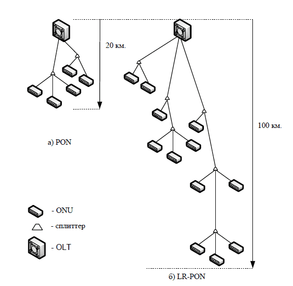
Figure 1 — Comparison of PON and LR-PON topology
The expanded functionality of LR-PON provides tangible savings in costs and incurred costs by reducing the number of required optical-electrical-optical signal conversions. Thus, the trend of PON development will lead to a modification of the structure of urban networks towards a reduction in the number of nodal stations. But there is also a downside to the coin. Increasing the distance between node devices in LR-PON leads to a number of problems, among which can be noted signal transmission, with a possible wavelength drift of 20 nm. This value was considered insignificant for traditional PONs, but a special solution is required for LR-PON, which is realized through the use of more expensive transmitters (rejective ONU technology – R-ONU)
The next issue to consider when deploying LR-PON is the need to amplify the signal as the distance to network nodes increases. This is accompanied by negative phenomena such as amplitude spontaneous emission (ASE), which is a by-product of erbium optical amplifiers (EDFA). To reduce the ASE effect, a dual stage intermediate gain is applied, as well as gain control, according to the specific distance to the node device. As the transmission range increases, the data transmission delay on request from the ONU increases. The established rates of delay in the access network are approximately 1-2 milliseconds for real-time applications. Algorithms for dynamic bandwidth allocation are being developed to keep the transmission latency within the norm. The tree topology used in traditional PONs is may have lower reliability than required. To increase reliability, a "ring with taps" topology is used, where all splitters are connected in a ring and have taps to the ONU.[6] An example of such a construction is shown in Figure 2.
Figure 2 — An example of building an LR-PON network according to the "ring with branches" topology
(animation: 8 frames, 8 repetition cycle, 197 kilobytes)
1.2 Basic components and signal paths in LR-PON networks
The heart of the entire PON network is an optical line terminal (OLT), which consists of a special multiplexer-demultiplexer (AWG, Arrayed Waveguide Grating – a grating made in the form of an array of waveguides), and an optical amplifier signal. AWG is an optical component that is a diffraction grating on or in a planar optical waveguide. The basic principle of AWG, which is involved in channel separation, is based on the occurrence phase differences for different wavelengths of the optical signal at the input and output.
Modified splitters are used within the networks under consideration. The difference between LR-PON splitters from conventional ones is the increase in the number of output ports (while maintaining the required power), which reaches 1х512. It became possible due to the use of more powerful amplifiers (in active network devices).
Due to the connection of the splitters in cascades (when implementing the tree with branches
or ring
topology), the negative impact of the temperature and wave dependence on the parameters of the splitter increases. The temperature dependence is small, but
it can be indirectly amplified through the wave dependence of the splitter, as well as through the temperature instability of the transmitter. The instability of the operating wavelength of the laser can reach 0.5 nm/C°. If the subscriber nodes do not support constant
temperature, then a seasonal shift of the operating point by 10 nm will lead to a redistribution of the radiation power (at the nominal wavelength) in the arms of the splitter by 0.3 dB (based on 0.03 dB per 1 nm shift – for floating splitters). Optical network device – ONU.
The receiving path of the ONU optical network device in LR-PON has practically not changed. The receiver of each ONU has a sensitivity of 24 dBm. ONU on the transmitting side in LR-PON are different, because use different types of optical signal amplifiers.
To transmit signals over the distribution section, the ONU uses SOA optical amplifiers, which are needed to transmit upstream traffic.[3]
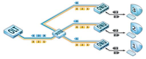
Figure 3 — Allocation of time intervals between ONUs
2. LR-PON network optimization criteria and methods
2.1 General information on optimization methods and performance criteria for data transmission networks
If it is required for the data transmission network to work as efficiently as possible, then it is necessary to determine the performance criteria and select a list of variable network characteristics.
The main criteria for the efficiency of a network are its performance and reliability, for which it is necessary to determine stable parameters for evaluation – response time and availability. It is also required to define a threshold indicator sensitivity for given performance parameters.
These editable parameters can be grouped in different ways. For example, they can be divided into parameters of any protocols or specific devices.
As a rule, network optimization is understood as a certain intermediate option, in which it is required to choose such values ??of the network parameters so that its efficiency indicators significantly improve.
All of the most commonly used criteria for network performance can be divided into two groups. One group characterizes the performance of the network, the second – reliability.
Network performance is measured using two types of metrics – time metrics, which measure the latency introduced by the network when exchanging data, and throughput metrics, which reflect the amount of information transmitted by the network per unit of time. These two types of indicators are mutually inverse.[5]
Since in networks, data on the way to the destination node usually passes through several transit intermediate stages of processing, then the capacity of a separate intermediate network element – a separate channel, segment or communication device. Knowing the total bandwidth between two nodes cannot give complete information about the possible ways to increase it, since from the total figure it is impossible to understand which of the intermediate stages of packet processing in slows down the network to the greatest extent. Therefore, data on the throughput of individual network elements can be useful for deciding how to optimize it.
The most important characteristic of a computer network is also reliability – the ability to function correctly over a long period of time. This property has three components: reliability itself, availability and serviceability.
Improving reliability consists in preventing malfunctions, failures and failures through the use of electronic circuits and components with a high degree of integration, reducing the level of interference, lightweight modes of operation of circuits, ensuring thermal modes of their operation, and also by improving equipment assembly methods.
2.2 Selection and analysis of the main criteria for optimizing the LR-PON network
The LR-PON network is a complex system, so a number of calculations based on various criteria must be made before designing it.
To ensure the ability to efficiently transfer data over the required distances, it is necessary to verify that the power budget of the devices and the budget of losses that will arise in the projected network should be checked. This correspondence is called energy balance. and is a fundamental criterion in the construction of an LR-PON network.
No less important is the reliability of the network, which ensures the quality of services provided to users. In addition, the indicated properties are closely related to the resource consumption of the system.
An integral part of network design is calculating its cost budget. The network cost budget directly ensures its compliance with all the requirements and is their fundamental basis.
Based on the foregoing, the energy balance, reliability and cost of the projected network are the main criteria for its optimization. The paper investigates the optimization of the LR-PON deployment according to the specified criteria. The calculations use linear programming methods.
2.3 Calculation of the energy balance of the network
To formulate the optimization problem, it is necessary to introduce the following notation:
- lв – length of optical fiber section from OLT to ONU;
- Aобщ – access network reliability;
- Cобщ – LR-PON deployment costs;
- Wобщ – power budget for LR-PON deployment.
The scale of the deployment of the access network can be changed depending on the requirements that are imposed on the characteristics under consideration. Then the problem of optimization of the access network in general form can be formulated as follows:
lвmax ->max; Aобщ ≤ Aдоп; Cобщ ≤ Cдоп; Wобщ ≤ 30.
where Aдоп, Cдоп – requirements for reliability and cost, respectively, and Wобщ ≤ 30 [dB] – power budget corresponding to the maximum length of the LR-PON line not exceeding 100 km. This value is due to the types of optical amplifiers used signal. Within the framework of the work, the power budget will be the upper boundary limit for optimization. When planning to install other amplifiers on the network, the fixed Wобщ parameter can be changed.[4]
2.4 Calculation of network reliability
When designing a network, one should also take into account the quality of service provision, which is determined by its reliability and is closely related to the total resource consumption of the entire network. The overall reliability of the entire designed system is calculated based on indicators reliability of all its components. In LR-PON networks, individual circuits are investigated, which represent OLT – splitter – ONU. Such a chain is inherently a series connection of elements. If we consider the relationship between such circuits, the connection will be considered parallel. Typically, the reliability of the entire system will be determined by the OLT – splitter – ONU chain with the lowest reliability index.
Passing to the probability of failure, we get:
Uобщ = 1-Aобщ = 1-П(1-Ui),
where Uобщ is the probability of network failure; Ui is the probability of failure of the i-th element of the most unreliable circuit OLT – splitter – ONU.
From the product of the probabilities of failures, one can proceed to summation:
1-П(1-Ui) ≈ ∑Ui
Based on the above formulas, for a network without redundancy we get:
Uобщ = UOLT+Uф*lф+N*Uсп+∑ Uпр*lk+Up*lm+UONU
where UOLT - OLT failure probability; Uф – probability of fiber failure at the OLT - splitter (feeder section) section, reduced to a length of 1 km; lф – length of OLT section – splitter; N – the number of splitters in the network; Uсп – splitter failure probability; Uпр – the probability of fiber failure in the splitter-splitter section (intermediate section), reduced to the length of 1 km; lk – length of k-section splitter – splitter; Uр – the probability of fiber failure in the splitter - ONU (distribution section) section, reduced to the length of 1 km; lm – length of the m-distribution section splitter - ONU; UONU – probability of ONU failure.
Assuming that the probabilities of fiber failure in any sections of the network are equal, we introduce the general notation Uв = Uф ≈ Uпр ≈ Uр. The length of the OLT – ONU section is determined by the value:
lв = lф+∑lk+lm
Then:
Uобщ = UOLT+N*Uсп+UONU+Uв*lв
For a fully redundant network, it is necessary to consider the additional installation of optical traffic switches from the main channel to the backup channel, which will contribute to the probability of failure.
2.5 Calculation of the cost of the planned network
The total LR-PON cost budget is the sum of the costs of all its nodes and elements. For a network without redundancy, we get:
Cобщ = COLT+Cф*lф+N*Cсп+∑Cпр*lk+∑lm*Cр+M*CONU+Cпнр
where COLT – OLT cost; Cф – cost of 1 km of fiber on the feeder section; Cсп – the cost of the splitter; Cпр – cost of 1 km of fiber in the intermediate section; Cр – cost of 1 km of fiber at the distribution section; CONU – ONU cost; M – number of ONUs; lm – length of the m-distribution section splitter – ONU; Cпнр – the cost of starting-up and adjustment works during network deployment.
To transmit all traffic, you can use the same type of optical cable, so the cost of fiber for different sections will be the same. Then Cв = Cф ≈ Cпр ≈ Cр.
Similarly:
Cобщ = COLT+N*Cсп+M*CONU+Cпнр+Cв(lв+∑lm).
For a fully redundant network, the cost of each device will double.
You also need to consider the cost of optical switches:
Cобщ = 2*COLT+2*N*Cсп+2*M*CONU+Cоп(N+M+1)+Cпнр+2*Cв(lв+∑lm)
Let's assume that the cost of commissioning is equal to the cost of the equipment being installed. With this in mind, for a network without redundancy, we get:
Cобщ = 2*COLT+2*N*Cсп+2*M*CONU+2*Cоп(N+M+1)+2*Cв(lв+∑lm).
2.6 Optimization problem solution
Let's compose systems of equations for the reliability and cost of network deployment:
Aобщ = 1-(UOLT+N*Uсп+UONU+Uв*lв), Ⅰ 1-(UOLT²+Uсп*N+UONU+Uоп+Uв*lв), Ⅱ 1-(UOLT²+Uсп²*N+UONU+Uоп(N+1)+Uв*lв), Ⅲ 1-(UOLT²+Uсп²*N+UONU+Uоп(N+1)+Uв²*lф+Uв(lв-lф)), Ⅳ 1-(UOLT²+Uсп²*N+UONU+Uоп(N+1)+Uв²(lф+∑lk)+Uв(lв-lф-∑lk)), Ⅴ 1-(UOLT²+Uсп²*N+UONU²+Uоп(N+2)+Uв²*lв), Ⅵ
Cобщ = 2*COLT+2*N*Cсп+2*M*CONU+2*Cв(lв+∑lm), Ⅰ 3*COLT+2*N*Cсп+2*M*CONU+Cоп+2*Cв(lв+∑lm), Ⅱ 3*COLT+3*N*Cсп+2*M*CONU+2*Cоп(N+1)+2*Cв(lв+∑lm), Ⅲ 3*COLT+3*N*Cсп+2*M*CONU+2*Cоп(N+1)+Cв*lф+2*Cв(lв+∑lm), Ⅳ 3*COLT+3*N*Cсп+2*M*CONU+2*Cоп(N+1)+3*Cв(lв+∑lm)-Cв*∑lm, Ⅴ 3*COLT+3*N*Cсп+3*M*CONU+2*Cоп(N+M+1)+3*Cв(lв+∑lm), Ⅵ
where Ⅰ – network option without reserve; Ⅱ – OLT redundant network option; Ⅲ – network option with OLT and splitters redundancy; Ⅳ – network option with redundant OLT, splitters and feeder fiber; Ⅴ – network option with redundant OLT, splitters, feeder and intermediate fibers; Ⅵ – full redundancy network option.
Conclusions
The growing demand of users for services requiring high data transfer rates every year leads to an increase in capital and operating costs for operators. The search for a reduction in these costs leads to the conclusion that
the need to switch to LR-PON technology, in which the access network extends up to 100 km or more. At the same time, the convergence of the access network and the city network occurs, the number of network devices (ONU) connected to the OLT increases
up to 1000 and more, conditions are created for the consolidation of OLT (approximately in the ratio of 1:50) in one room, called the central office
.
The construction of LR-PON, as a rather complex system, is preceded by detailed calculations according to various criteria, among which the most important role is played by the balance of power, cost and reliability. Each of the criteria can be calculated, based on the methodology described in the second section. The final calculation of the optimization problem was a system of equations, which took into account various types of redundancy and the presence of main network devices.
References
- Иванов В.И. Применение технологии WDM в современных сетях передачи информации: учеб. пособие для студ. выс. уч. заведений. Казань, 2010. – 148 с.
- Шувалов В.П., Фокин В.Г. Пассивные оптические сети большого радиуса действия. М.: Горячая линия – Телеком, 2018. – 154 с.
- Игнатов А.В. Энергетические условия развертывания LR-PON // Современные проблемы телекоммуникаций: материалы Российской научно-технической конференции (г. Новосибирск, 23-24 апреля 2015 г.). Новосибирск, 2015. – С. 147-149.
- Аверченко А. П., Воропаев В. К., Веприкова Я. Р. Затухания в идеальном оптоволокне // Молодой ученый. – 2017. – №43. – С. 29-31. – Режим доступа: https://moluch.ru/archive/177/46090.
- Фролов Р.А. Оптимизация использования пропускной способности // Технологии и средства связи. 2007. – №3. – С. 56-58.
- Олифер В.Г. Компьютерные сети. Принципы, технологии, протоколы: Учебник для вузов. 3-е изд. / Н.А. Олифер. – Питер, 2009.
- Шувалов В.П, Ионникова Е.П., Яковлев А.С. Особенности оптических сетей доступа большого радиуса действия [Электронный ресурс] – режим доступа: https://cutt.ly/4hrF13D - дата доступа: ноябрь 2020.