
Abstract on the topic of graduation work
Content
- Introduction
- 1. Relevance of the topic
- 2. Goal and tasks
- 3.Characteristics of a mine boiler plant as a technological object of automation
- 4 Review of existing technical solutions for ratio control
fuel–air
mine boiler plant automation - 5 Ways to improve the efficiency of the automatic ratio control system
fuel–air
mine boiler plant automation - 5.1 Algorithmization of the automatic ratio control system
fuel–air
mine boiler plant automation - ?onclusions
- List of sources
Introduction
Today, the issues of heat power engineering are the most relevant and occupy the most important place in the world. The main tasks are to ensure comprehensive processing of raw materials, the creation of resource-saving equipment and technologies, and a sharp reduction in losses and waste. At the moment, a situation has arisen when thermal stations are experiencing an urgent need to modernize technological equipment and especially technological control and management. The introduction of a new line of control devices and actuators made it possible to significantly improve the reliability, maintainability and economic benefits of the boiler plant for the heat supply of the mine.
1. Relevance of the topic
In recent years, restructuring of the fuel mix to reduce dependence on oil and gas has revived interest in coal in many countries. In this period, the information and requirements are met by boiler plants that run on solid fuel. Ratio regulation fuel–air
provides the necessary conditions for fuel combustion. Coal must be burned economically, coal combustion is organized so that the best heat exchange conditions are maintained in the furnace.[1]
2. Goal and tasks
Taking into account the tendency to decrease the productivity of the boiler plant, the purpose of the work – improving the efficiency of the mine boiler plant operation.
The general purpose of the work is the following tasks:
- Analysis of existing technical solutions in the field of automation of a mine boiler plant operating on solid fuel.
- Research of technological features of a mine boiler plant.
- Development of a mathematical model for the process of production and distribution of heat energy.
- Improvement of the automatic ratio control system
fuel–air
. - Development of technical solutions for the implementation of an automatic ratio control system
fuel–air
.
3. Characteristics of a mine boiler plant as a technological object of automation
The technological scheme of a boiler plant with a layered furnace is shown in Figure 1.
Boiler installations – one of the largest consumers of heat in mines, carrying out the process of heat supply to the mine during the cold season. Boiler room – a system in which the heating medium for the heating system is heated. The main elements of this installation are: boiler, burner, control system, power supply and gas ducts.[8]
A boiler – is a device where heat exchange occurs between hot products of fuel combustion and water. Boiler control system – a special control unit that organizes the entire complex of the system's work, carries out a certain order of actions, which is set by the program's algorithm. Feeding devices are needed to supply water to the boiler.[2]
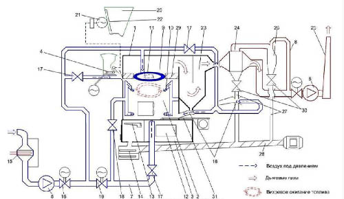 Figure 1 – Boiler plant flow diagram
1 – boiler block, 2 – layer furnace, 3 – firebox TSHIP–2,5, 4 – coal feeder,5 – fan,6 – smoke exhauster, 7 – air ducts, 8 – chimneys, 9 –afterburner, 10 – tangential secondary blast nozzles, 11 – annular nozzle, 12 – hole, 13 – lattice, 14 – SHZU conveyor, 15 – heater,16 – general blowing valve, 17 – air supply gate for coal feeder, 18 – IED nozzles, 19 – bottom blow valve, 20 – coal bunker, 21 – vibrator, 22 – conveyor belt, 23 – conveyor bundle, 24 – straight-through cyclone, 25 – chimney, 27 – ash discharge risers, 28 – ash removal auger, 29 – pinch, 30 – ash removal gate, 31 – rustling bar.
The draft mechanism is a single system of blowing fans, gas ducts, chimney and smoke exhausters, which help in supplying air to the furnace and move combustion products through the boiler gas ducts, and after – their removal into the atmosphere. The combustion products give off heat to the water when they move along the gas ducts and touch the heated surface.
To ensure rational use, boiler plants have additional elements: water and air economizers, devices for fuel supply and ash removal. There are also functions for cleaning flue gases and feed water, instruments for monitoring automation equipment, which ensure reliable and uninterrupted operation of all links.
Layer furnace – a furnace for layered combustion, a furnace or a steam boiler, in which the combustion of fuel, loaded with a layer on the grate, occurs in a stream of air penetrating this layer (usually from the bottom up). This furnace consists of a grate that supports a layer of lumpy fuel and a furnace space in which flammable volatiles are burned.[4, 5]
Layer furnaces are designed for burning solid lump fuel. They are easy to operate, suitable for various types of fuel, do not require large volumes of the furnace, can operate with significant fluctuations in heat load, differ in relatively low energy consumption for their own needs and, most importantly, do not require expensive dust preparation devices.
The mnemonic diagram (Figure 2) shows – boiler, hopper, grate, conveyor, 2 fans, smoke exhauster, feed pump. Buttons:
- open, close the grate;
- increase, decrease the fan speed;
- start, stop, accident, fire;
- manual control, automatic control.
 Figure 2 – Mnemonic diagram of a mine boiler plant with a layer layer
(animation: 8 frames, endless cycles, 136 kilobytes)
4. Review of existing technical solutions for ratio control fuel–air
mine boiler plant automation
Boiler rooms are automated according to a two-level control scheme. The first level includes devices of local automation, PLC, which provide protection and blocking, adjustment and change of parameters. This also includes the equipment that is necessary for the transformation, coding and transmission of information.
The upper level is presented as a graphical terminal built into the control cabinet or a PC-based operator. There, all the information that comes from the low-level microcontrollers and system sensors is provided, and operational commands, adjustments and settings are entered. In addition to scheduling the process, the tasks of optimization of modes, diagnostics of technical conditions, analysis of economic indicators, archiving and data storage are solved. Also, information can be transferred to the general management system of the enterprise (MRP / ERP) or settlement.[3]
The automation system of the boiler plant must perform control and information functions.
Control functions:
- automatic control of boilers in accordance with regime cards;
- automatic maintenance of a certain air temperature at the outlet of the boiler plant.
In addition to automatic control, there is also control in manual mode from local control posts and in remote – from the operator's console.
Informational functions:
- control of the current values of the parameters of the coolant and air;
- monitoring the state of the mechanisms of boilers and general boiler equipment.
The use of a PLC makes it possible to significantly reduce the cost of cable products, thanks to digital data transmission and control channels, the time spent on installation and commissioning is reduced. Implementation of automatic control of boilers and a dispatch system allows reducing the required number of working personnel to two people: an operator and a locksmith during the day shift and 1 operator during the night.[6, 10]
Characteristics of the air heating installation according to the boiler–heater scheme:
- volume of supplied air – 240 /s;
- minimum supply air temperature – +2-+5;
- minimum cold air temperature 45 ;
- useful heat output up to – 15 Gcal / hour (17.5 MW);
- maximum consumption of coal VNU during the operation of three boilers up to – 3t / hour;
- slag and ash output during operation of three boilers up to – 600kg / hour.
At present, the system "Kontur 2" is used as an automated control device for the combustion process, which provides control of the solid fuel supply to the furnace based on the boiler load with temperature correction, maintaining the normal ratio of fuel and air, maintaining the required stable vacuum in the furnace. The KONTUR 2 equipment is one of the known equipment for automating a boiler plant and the process of heat supply to a mine. It consists of primary devices, regulating blocks and executive devices. The parameters of the boiler operation, which provide automatic control by the KONTUR 2 equipment, are:
- regulation of the ratio
fuel–air
; - regulation of steam pressure in the boiler drum;
- regulation of vacuum in the boiler furnace;
- regulation of the water level in the boiler furnace.
Pressure transducer OWEN PD150 – the device is designed to combine the function of a primary measuring sensor and a secondary indicating device. It is necessary in order to control the pressure of non-aggressive, combustible and flue gases. It creates power control and information signals for control automation.
Motor electric actuators of the MEO type are made on the basis of a single design and they consist of an electric motor, a reducer, a manual drive, a brake, a sensor unit (feedback rheostats), a stop unit, and a lever.
5.Ways to improve the efficiency of the automatic ratio control system fuel–air
Boiler room is a structure where the latest ideas in the field of heat engineering and automation are being introduced, the heat carrier is heated for heat and steam supply systems. When choosing controlled quantities, it is necessary to be guided by the fact that with a minimum number of them, the most complete picture of the process was provided. Subject to control are those parameters, according to the values of which the operational control of the technological process, as well as its start and stop, is carried out. These parameters include all operating and output parameters, as well as input parameters, when changed, disturbances will enter the object.
Automatic regulation of the ratio of the consumption of coal and air should provide the necessary conditions for coal combustion. Conditions coal – must be burned economically, the combustion of coal must be organized so that the best heat exchange conditions are maintained in the furnace[7].
Numerically fuel ratio –air is determined by the so-called air flow rate. Monitoring the air pressure after the blower fan is necessary to determine the fan operation. A decrease in air pressure occurs in the event of a fan shutdown or closing of its guide vane in the event of a malfunction of the air regulator. When the air pressure drops, the flame can be detached or extinguished. Since at the moment the fan is turned off, air does not enter the furnace, the vacuum increases, and the torch detaches.
The air flow rate is:
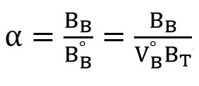 Formula 1 – Air flow rate
WhereB – actual air flow; BB° – theoretical air flow, necessary for complete combustion of fuel; VB° – theoretical amount of air required for complete combustion of a unit of fuel; T° –fuel consumption.
Automatic regulation of the ratio of fuel and air consumption is carried out using ratio regulators. Most often, the leading flow in the heating and automatic proportioning circuit is fuel, the flow rate of which is set by the temperature controller. The ratio regulator receives information about the fuel and air flow rates and controls the air flow rate, which is thus the slave flow.In some cases, the reverse scheme is used, where the leading flow is air, and the driven – fuel.
Ratio control methods fuel–air
:
- outlet flap adjustment;
- gate regulation at the entrance;
- fan regulation.
5.1 Algorithmization of the automatic ratio control system fuel–air
mine boiler plant automation.
A block diagram of the algorithm is shown in Figure 4.
The automatic control of the boiler plant provides:
- switching on and off the magnetic smoke exhauster starter;
- switching on and off the magnetic starter of the blower fan;
- switching on and off the magnetic starter of mechanical casting;
- turning on and off the inflammatory electrode of the burner;
- control of the operating parameters of the boiler plant;
- ratio regulation
fuel–air
; - overheating protection of the electric motor;
- providing emergency signaling;
- transfer of information to an industrial computer network.
At the first stage of control, the PLC is initialized, the necessary system parameters are entered using the IP320 operator panel. Interrogation of sensors and comparison of readings between received and required. If the read poll is greater than the specified one, the polling of the sensors continues. Otherwise, the PLC proceeds to the next action. Based on the entered initial parameters, you need to determine whether autorun is enabled or not. If autorun – switched on, then the boiler goes into manual ignition mode.
In the ignition mode, the heating of the tubular electric heater starts, the fan starts, and the guide vane opens. Further, it is necessary to obtain a flame in the burner, in order to detect the presence of a fire in the burner, the flame sensor is interrogated. If there is no flame, ignition continues. If there is a flame, then the system goes to work.
After that, the coal is conveyed to the boiler furnace bunker. In manual ignition mode, heating starts. It is necessary to get a flame in the burner.
In the operating mode, the process of maintaining the burning state of the fuel occurs, while the readout temperature should increase.
In ratio adjustment mode fuel–air
we manage the consumption of coal and air. The task of this mode is to maintain the ratio within the specified range.
If the temperature becomes lower than the set one, then the boiler switches to interrogating the sensors, after which the boiler enters either the ignition mode or the operating mode. If the temperature is higher than the set one, then the extinguishing mode is set. After starting the system, the set value mode is set «P°» – 8 atmospheres, ? «t°» – 110 degrees.
If the parameter Q deviates, a corresponding decrease or an increase in the supply of air and fuel is ensured, if everything is normal, the boiler continues to operate under the specified conditions and the measuring cycle is repeated. C = 1 – the presence of an alarm or a technological stop. When an alarm occurs, a signal is sent to the operator's control panel to turn off the boiler and, accordingly, the fuel and air supply stops.[9]
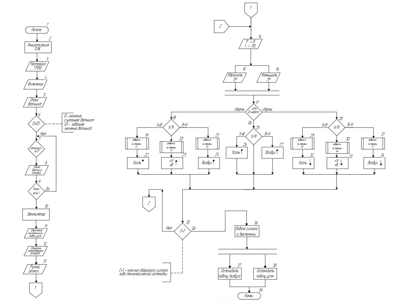 Figure 3 – Block diagram of the ratio control algorithm
 fuel–airmine boiler plant
Conclusions
In the abstract, a mine boiler plant was considered as an object of automation, an algorithm was proposed for automatic regulation of the ratio fuel–air
. There is a need to improve the efficiency of the mine boiler plant by introducing an automatic control system. In this case, it is necessary to maintain a certain temperature of the coolant and optimal use of fuel. To complete it, you need to install the necessary set of elements for the future boiler house and their order of work, which I will continue in my future work.
When writing this essay, the master's work has not yet been completed. Final completion: June 2021. Full text of the work and materials on the topic can be obtained from the author or his manager after that date.
References
- Котельные установки промышленных предприятий – Сидельковский Л.Н. Юренев В.Н.
- Батицкий В.А., Куроедов В.И., Рыжков А.А. – Автоматизация производственных процессов и АСУ ТП в горной промышленности. – М.: Недра, 1991.
- Теория автоматического управления / Лукас В.А. – М. 1990 г.
- Температурные измерения. Справочник. /Геращенко О.А., Гордов А.Н., Еремина А.К. и др.: Отв.ред. Геращенко О.А.–Киев: Наукова думка, 1989.-709 с.
- Курносов, В. Г. Научные основы автоматизации в угольной промышленности: опыт и перспективы развития: монография / В. Г. Курносов, В. И. Силаев; Междунар. ин–т независимых пед. исслед.
- МИНПИ – ЮНЕСКО, ОАО «Автоматгормаш им. В. А. Антипова». – Донецк: Вебер, Донец. отд–ние, 2009.
- Шафрановский, В. А. Справочник наладчика автоматики котельных установок / В. А. Шафрановский. – Симферополь: Таврия, 1987. – 176 с
- Хуторной, А. Н. Котельные установки / А.Н. Хуторной. – Учебное пособие. – Томск: ТГАСУ, 2016. – 220 с.
- Кравцов, В. В. Экономическое использование угля в теплоэнергетике / В. В. Кравцов, А. Г. Махмудов, А. В. Харченко. – Донецк: ДонГТУ, 1999. – 320 с.
- Компания ОВЕН – ведущий российский разработчик и производитель контрольно–измерительных приборов и средств автоматизации для различных отраслей промышленности.