Abstract
Content
- Introduction
- 1. Theme urgency
- 2. Goal and tasks of the research
- 3. Analysis of the research object
- 4. The results of the research
- Conclusion
- References
Introduction
Carrying out work in a mine or mine, creating comfortable conditions in underground workings depends on the operation of the ventilation system, which includes a ventilation network, a main ventilation fan unit, heating units, local ventilation fans, and means of monitoring the state of the mine atmosphere.
1. Theme urgency
Currently, automation of fan installations is understood as remote control of fans and devices for reversing the air stream and monitoring the operation of the installation. The automation equipment must perform the following functions: fan performance control; automatic switching on of the backup fan when the working fan is turned off; restart when the power supply voltage is restored; reverse of the ventilation jet [1].
The progress of the modern mining and coal industry puts forward a number of new requirements for ventilation systems in mines. The intensification of technological processes of underground mining, an increase in the speed of movement of treatment faces cause an increased influx of harmful emissions into the mine atmosphere, a more rapid change in the structure of the ventilation network and the aerodynamic resistance of mine workings. Mining operations at ever greater depths also lead to an increase in gas emissions and deterioration of climatic conditions due to an increase in the return of heat to the atmosphere of the mine workings from the surrounding rocks [2].
Thus, the topic of the masterʼs thesis is relevant.
2. Goal and tasks of the research
Goal of the research – improving the efficiency of the technological process of ventilation of mine workings by developing an automated control system for the distribution of air flows in the mine ventilation system.
Main tasks of the research:
- analysis of mine ventilation system as an automation object;
- analysis of existing developments on mine ventilation network automation;
- development of a mathematical model of automated control;
- development of structural and functional schemes of the automated control system, its operation algorithm;
- development of the principal scheme of the automated control system, creating a maket.
3. Analysis of the research object
The mine ventilation network includes mine workings and structures through which air moves, as well as workings, ventilation structures and worked space through which air seeps in such quantities that it affects the ventilation of the mine [3].
Ventilation of the mine is carried out by creating an air flow in the network of mine workings. The accepted direction of air flows in the network determines the scheme of ventilation of the mine and its individual sections. Currently, most mines use a Central ventilation scheme with a suction method, in which a fan at the mouth of the shaft that issues air creates the vacuum necessary for air movement. Figure 1 shows a fragment of the mine workings ventilation system [4].
Main fan installations, local ventilation fans, mine ventilation network, regulated and unregulated ventilation devices, heaters, air conditioners make up the ventilation system.
Air from the atmosphere through the feed barrel FB (cage trunk) enters into the mine. If necessary, it is heated using a heater H (in winter). Stream is branched in the unloading yard and supplied to the haulage drifts in Western and Eastern wing. The flow rate of air through the workings is changed by means of adjustable ventilation devices AVD. They are adjustable throttle devices installed in crossings and bypass ventilation workings. Since the airing scheme is symmetrical, we will follow the movement of the air jet only along the East wing. After passing the third adjustable vent device AVD3, the jet splits: part of the air enters into the Eastern lava No. 1, and part of it enters into incline. A certain amount of air entering the incline is used to ventilate the face of the intermediate drift using a local ventilation fan LVF. The exhaust air is collected at the Eastern vent drift VD and through the vent shaft (or skip shaft) S is released into the atmosphere by the main fan instalation FI.
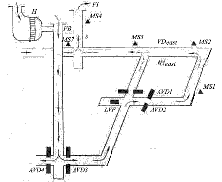
Figure 1 – Fragment of the mine workings ventilation system
The percentage of methane in mine workings is monitored by methane sensors MS. The location of their installation and the maximum percentage of methane is regulated by Instructions for the air gas control system in coal mines
.
The percentage of methane is the main, but not the only criterion for determining the amount of air supplied to various mine faces. The air velocity in the mine workings and dust formation are very importan. The air supply to the workings is controlled by sensors. The amount of air entering the places of the highest intensity of work should not be less than a certain value Qmin, regulated by Safety rules in coal mines
. The Qmin value is not a constant value and depends on the nature of the shift (mining or repair), the effectiveness of dust suppression, the volume of drilling and blasting operations, and so on. The ventilation system should be supplemented with air quantity sensors with their installation in places of the highest intensity of work to monitor Qmin at low methane emissions.
The controlled parameter of the control system is the amount of air supplied to the face, and the disturbing effects are the percentage of methane, the amount of harmful gases released during drilling and blasting, the intensity of dust formation, etc.
There are two ways to improve the efficiency of airing gas coal mines:
- increase in the cross-sections of mine workings, transition to more rational ventilation schemes, in which methane released from various sources in the system of mine workings is diluted by separate air flows. The main obstacle to solving the problem is the need for additional workings, which is associated with economic costs. In addition, an increase in the speed of air movement in certain areas of workings can lead to deterioration of working conditions due to dustiness of the workplace.
- operational control and management of ventilation mode. Efficiency is achieved by increasing the carrying capacity of each cubic meter of air supplied to the mine workings, with a minimum of the above costs.
The process of ventilation of the mine is strictly regulated Safety rules in coal mines
[5] and other regulatory documents. In normal mode, the ventilation system must supply and distribute the amount of air that is required in accordance with the safety rules in coal mines (SR) to ensure comfortable and safe working conditions for miners, to ensure the specified productivity of the faces with the existing parameters of the mine atmosphere: gas release, dust formation, heat and humidity, under optimal operating conditions of fan installations.
In mining operations and the excavation passages the aerodynamic drag is continuously changing. In this case the deviation of the actual airflow into each passage of the ventilation network takes place from a predetermined value in an upward or downward direction. As a result of this process there may not be enough air in one of the passages of network, whereas in another passage there will be an excess of air, which is forbidden by safety rules. Therefore, it is necessary to develop an automated control system for the technological process of ventilation of mine workings in such a way that it redistributes air flows. The problem of air flow redistribution was considered by Zavadskaya Tatyana in the article Block-oriented model of a multi-connected air distribution control system in a mine ventilation network
[6].
Dredging sites are the main objects of ventilation in coal mines. Depending on the load on the excavation site, it is necessary to provide it with the appropriate amount of air. Therefore, there is a need to redistribute air flows [7,8]. The structural diagram of the connection of the ACS to the ventilation system of the excavation site (SVES) is shown in fig.2, and the structure of the ACS is shown in fig.3.
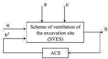
Figure 2 – Block diagram of an automated SVES

Figure 3 – Structure of the branch air flow control system: 1 – determinant Δ Q; 2 – relay amplifying element; 3 – engine; 4 – reducer; 5 – regulatory body; 6 – SVES (object); 7 – sensor[7,9,10]
When the aerodynamic drag R/ decreases, the engine moves the regulator. The angle of regulatory body installation α decreases, the difference between the actual and required flow rates Δ Q increases, and the air flow rate Q in this branch increases. When R/ increases, the engine runs in reverse mode, α increases, and the air flow Q decreases. This principle of redistribution was taken as a basis for the development of an automated control system for the technological process of ventilation of mine workings.
4. The results of the research
Figure 4 shows a flowchart of the air flow adjustment.
During operation air distribution automated control system in the mine ventilation network determines the state of the mine atmosphere in each passage of the ventilation network, pointing out the passage with the highest air shortage. After that the position of the regulatory mechanism in this passage is determined. If the damper is closed or in an intermediate position, the control signal is sent to open it. When the barrier is fully open, the amount of air entering the passage with a shortage is regulated by overlapping adjacent passages, in case of safe regulation of excess air, the damper being in the open or intermediate position.
If there is no regulation reserve in the adjacent passages of the network and there is insufficient air in the regulated passage the overall consumption is increasing by opening the main ventilation fan guide device.If there no insufficient air passage and another passage having excess air, the overall air consumption is reduced by closing the main ventilation fan guide device. It will result in air redistribution between passages and detection of the network passage with air shortage.
To reduce the number of commutations of actuators, a dead zone (2-3%) is introduced together with time delay to redistribute air in the network passages after determining the actuator control signal (barrier or guide device).
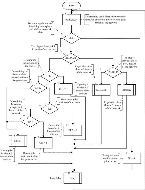
Figure 4 – Flowchart of the airflow adjustment
Figure 5 shows a block diagram of the automated air distribution control system in the ventilation shaft. There are airflow meter SDSV 01.01.01-M, a programmable controller TX9042 and air barriers in the mine workings. The signal from the SDSV 01.01.01 M enters the TX9042. The TX9042 is powered by the PM-6321/13.5-A.01. The information from the TX9042 is transmitted through RS-485 Modbus protocol to a programmable logic controller PLC150-220, which is located on a remote control of the mine manager. The airflow meter SDSV 01.01.01 M and PD150-DI10,0K pressure converter are disposed in the suction channel to measure airflow of an outgoing jet and the vacuum value connected to PLC150-220.
The touch panel controller with Ethernet SPK107 [M01] is designed for visualization and control of the technological process of ventilation of mine workings. The SPK107[M01] is connected to the PLK150-220 via an Ethernet network. Air flow rate and vacuum adjustment in the mine workings are carried out by affecting PLC150-220 and TX9042 on the main ventilation fan guide device and ventilation barriers.
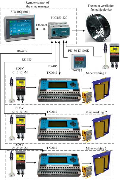
Figure 5 – Block diagram of the automated air distribution control system in the ventilation shaft
To confirm the system efficiency the model of the mine ventilation network was elaborated. Figure 6 is the technological scheme of the system. The fan 1 makes a directed air flow taken from the atmosphere through the inlet 14. The flow is distributed into three parallel passages. Speed sensors 2,5,8,11 measure flow rate at the outlet of the ventilation network and in parallel passages respectively. Dumpers 3,6,9,12 are designed to change the ventilation network resistance and at the same time they are the sources of disturbing influence. The programmable logic controller PLK150-220 sets the required network resistance by affecting the controlled barriers 4,7,10,13. The degree of closing dumpers is determined by the resistive position sensors 15-22. Air pressure is measured by pressure converters PD150-DIV200P installed at the entrance to the ventilation network 23, at the intersection of parallel passages 24, 25 and at the exit from the network 26.

Figure 6 – Flow diagram of the maket of the mine ventilation network
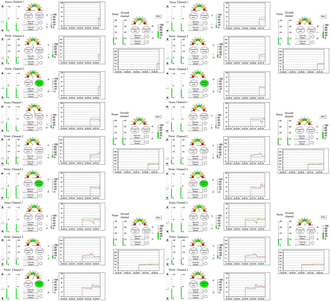
Figure 7 – Dispatcherʼs control panel (animation: 6 frames, 10 repetition cycles, 142 kilobytes)
Conclusion
Based on the conducted analysis, literature review, study of the modern state of the circuitry automation fan installations of the main airing, was based on the algorithm of automation and developed a block diagram of automated control system of air distribution in the ventilation system of the mine, and a structural concept of the system that allows rapid remote control mining Manager, control of the performance of the main ventilation fan unit and the distribution of air volumes in three major workings.
To confirm the system efficiency the model of the mine ventilation network was elaborated, with which you can study the process of distributing the air flow in three parallel branches when their aerodynamic resistance changes, and train students to perform software implementation of regulation.
When writing this paper, the masterʼs thesis is not yet completed. Final completion: June 2021. The full text of the work and materials on the topic can be obtained from the author or his supervisor after the specified date.
References
- Батицкий, В. А. Автоматизация производственных процессов и АСУ ТП в горной промышленности / В. А. Батицкий, В. И. Куроедов, А. А. Рыжков. – Москва : Недра 1991. – 303 с
- Толпежников, Л. И. Автоматическое управление процессами шахт и рудников. – М.: Недра, 1985. – 352 с
- Аэрология горных предприятий / К. 3. Ушаков [и др.]: Учебник для вузов. – 3-е изд., перераб. и доп. – М.: Недра, 1987. – 421 с.
- Конспект лекций по дисциплины
Автоматизация технологических процессов и производств
(для магистрантов очной и заочной форм обучения по направлению подготовки 15.04.04Автоматизация технологических процессов и производств
, магистерская программаАвтоматизация технологических процессов и производств в горно-металлургической отрасли
) / сост : А. С. Оголобченко. – Донецк : ДОННТУ, 2017. – 19с. - Правила безопасности в угольных шахтах [Электронный ресурс] : утв. приказом Гос. Комитета горного и тех. надзора ДНР и Мин-вом угля и энергетики ДНР 18.04.2016 г. № 36/208 : ввод в действие 17.05.2016. – Донецк, 2016. – Режим доступа: http://mintek-dnr.ru/zue/pravila_bezopasnosti_na_ugolnykh_shakhtakh.pdf – Загл. с экрана
- Завадская, Т. В. Блочно-ориентированная модель системы многосвязного управления воздухораспределением в шахтной вентиляционной сети//Зб. наук. пр. Донецького національного технічного університету. – Донецьк: ДонНТУ. – 2008. – Вип.7(150) – 290 с.(сер.:
Проблеми моделювання та автоматизації проектування
) - Абрамов, Ф. А. Моделирование динамических процессов рудничной аэрологии / Ф. А. Абрамов, Л. П. Фельдман, В. А. Святный – Киев: Наук. думка, 1981.
- Абрамов, Ф. А. Автоматизация проветривания шахт / Ф. А. Абрамов, В. А. Бойко – Киев: Наук. думка, 1967
- Святный, В. А. Моделирование аэрогазодинамических процессов и разработка систем управления проветриванием угольных шахт: дис. на соискание науч. степени док. техн. наук: 05.13.07 / В. А. Святный;– Донецк, 1985. – 440 с.
- Теория автоматического управления / Л. С. Гольдфарб [и др.] – Москва: Высшая школа, 1968.


 DonNTU
 Mastersʼ portal