
Abstract
Содержание
- Introduction
- 1. Purpose and objectives of the study
- 2. Literature Review
- 2.1. Basic principles of radio wave propagation in the atmosphere
- 2.2. Peculiarities of multi-slot waveguide antennas construction
- 3. Calculation and simulation of the waveguide-slot phar in the FEKO software
- Conclusion
- References
Introduction
Waveguide-slot antennas, obtained by cutting slots in waveguides, they are a type of linear (flat) multi-element antennas and provide a narrowing of the directional pattern (DN) in the plane passing through the axis of the waveguide.
The main advantages of such antennas are: - Due to the absence of protruding parts, the radiating surface of the waveguide-slot antenna can be combined with the external contours of the aircraft hull, without introducing additional aerodynamic resistance (on-board antenna); - In such antennas, the field distribution in the boom can be selected in a wide range, so the optimal DNS can be realized; - The slot antenna has a relatively simple excitation device. In addition, it is easy to operate.
One of the drawbacks in waveguide-slot antennas is their limited range properties. When the frequency in a scanning waveguide-slot antenna changes, the beam deviates in space from a given position, accompanied by a change in the width of the radiation pattern and its alignment with the feeder.
1. Purpose and objectives of the study
The purpose of the thesis is to design a waveguide-slot phased antenna array of the microwave range.
The main objectives of the study are:
- Consider the main features of microwave radio wave propagation used in waveguide-slot antennas;
- Study the basic concepts and features of phased antenna arrays;
- To design a waveguide-slot phased array of the microwave range.
2. Literature Review
2.1. Basic principles of radio wave propagation in the atmosphere
The propagation of radio waves in the atmosphere depends on the following main factors: wavelength, ground curvature, the nature of the ground, atmospheric composition, time of day and year, the state of the ionosphere, the magnetic field of the earth, and meteorological conditions.
In the atmosphere surrounding the globe, there are two areas that influence the propagation of radio waves: the troposphere and the ionosphere. The troposphere is the surface layer of the atmosphere, extending to an altitude of about 10 - 15 km. The troposphere is heterogeneous both vertically and along the Earth's surface. Its electrical parameters depend on meteorological conditions.
Ionosphere is a region of the atmosphere within 60 km - 300 km above the Earth's surface [1]. At these heights gas density is very low and gas is ionized, that is, there is a large number of free electrons (about 10^3 - 10^6 electrons in 1 cm3 of air). The presence of free electrons significantly affects the electrical properties of the gas and causes the possibility of reflection of radio waves from the ionosphere [1].
Thus, there are two types of radio waves according to the way they propagate in the atmosphere: - surface; - spatial.
Surface radio waves are radio waves that propagate directly above the surface of the Earth and envelope it due to the phenomenon of diffraction, as shown by curve 1 in Fig. 1.1 [1]. Spatial radio waves are divided into tropospheric and ionospheric.
Tropospheric radio waves propagate due to reflection or scattering from inhomogeneities (or "grains") of the troposphere, as shown by curve 2 in Figure 1.1.
Ionospheric radio waves propagate by means of multiple reflections from the ionosphere and the Earth's surface (curve 3 in Fig. 1.1). Due to the fact that the ionosphere is a heterogeneous medium, radio waves are scattered in it, it makes it possible to propagate radio waves over long distances.
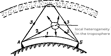
Figure 2.1 – Paths of radio waves in the atmosphere
In the ionosphere radio waves can be reflected, absorbed, as well as change their trajectory. Under the influence of alternating field of incident wave, free electrons of ionosphere make oscillatory motion and currents appear in ionosphere. Currents of positive ions are usually neglected due to their low mobility compared to electrons. During movement, electrons collide with molecules and give them kinetic energy derived from the radio wave field. The energy of the radio wave is converted into thermal energy. Long waves in the ionosphere are absorbed more than short waves, because the longer the wave, the more distance the electrons travel during oscillations for half a period, the more collisions occur on this path and the greater the absorption.
2.2. Peculiarities of multi-slot waveguide antennas construction
Multi-slot waveguide antennas are arrays of many radiating slits fed by a common waveguide, and are mainly used as on-board omnidirectional antennas. Half-wave resonant slits, placed in various ways on the wide or narrow walls of a conventional rectangular waveguide with wave type H_(10 ), are most commonly used[3].
A single slot in the waveguide is excited when its wide side crosses electric currents flowing on the inner surfaces of the waveguide walls. When an H_10 wave propagates in a rectangular waveguide, there are two magnetic field components [3]:
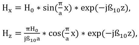
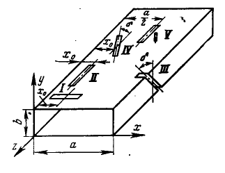
Figure 2.2 – Types of slots used in waveguide-slot antennas
The location of the cross-shaped slot to the right or left relative to the waveguide axis allows choosing right or left rotation of circular polarization. Cross-shaped slits can also be made of two obliquely displaced slits with a common center, oriented at an angle = 45° and perpendicular to each other. Such slits have more constructive possibilities.
Special reactive elements are sometimes used to excite the slots in the waveguide. Consider, for example, longitudinal half-wave slots 5, located exactly along the middle line of the waveguide as shown in Fig. 2.2. To excite such slots, capacitive pins with an adjustable depth of immersion in the waveguide (on a thread) are installed near their center. The field of the propagating wave H10 induces electric current in the pin, as in the receiving asymmetric vibrator. This current continues on the broad wall of the waveguide, spreading radially around the base of the pin. Part of the current crosses the slot and excites it. The direction of the current is reversed by moving the pin to the other side of the slot. Then the excitation phase of the slot will change by 180° as compared to the previous case [4].
Figure 2.3 – Operating principle of the waveguide slit PHAR
Any radiating slot loads the waveguide and affects its mode. Part of the power going through the waveguide is radiated by the slot, part is reflected back to the generator, and part goes further. When analyzing the response of the slot to the waveguide the latter is replaced by an equivalent two-wire transmission line of unit characteristic impedance, and each slot is assigned a four-pole lossy substitution diagram.
The value of normalized resistance is calculated by the methods of electrodynamics, based on the power balance in the real waveguide with a slot in its substitution circuit. The result is an approximate formula:
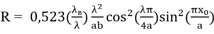
where x0 is the distance from the center of the slot to the edge of the wide wall.
3.Calculation and simulation of the waveguide-slot phar in the FEKO software
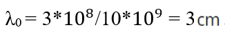
According to the task, the operating frequency range is 10 GHz. Let's calculate the supply line for the central frequency f0 = 10 GHz.
For the working wavelength [5]:

By substituting the values we obtain:
According to the calculations of the waveguide was selected waveguide WR-102.
Let's calculate the lengths of the slot antennas:
L=N*d
L = 2*18,952=37,904 (мм),
L = 4*18,952=75,808 (мм),
L = 8*18,952=151,616 (мм),
L = 16*18,952=303,232 (мм).
Modeling of the waveguide-slot PHAR was performed in the FEKO software product designed for the design and electrodynamic modeling of three-dimensional microwave devices, based on several calculation methods.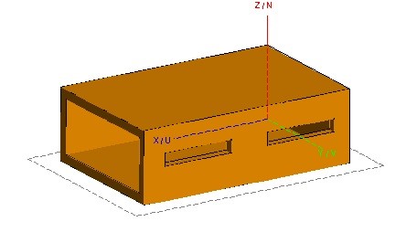
Figure 3.1 – Model of the waveguide with 2 slots.
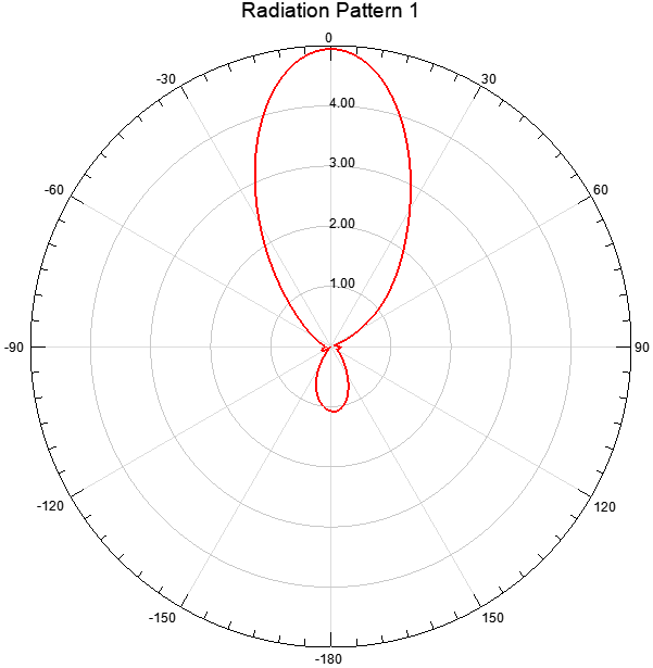
Figure 3.2 – Directional diagram of the waveguide-slit PHAR with 2 slits.
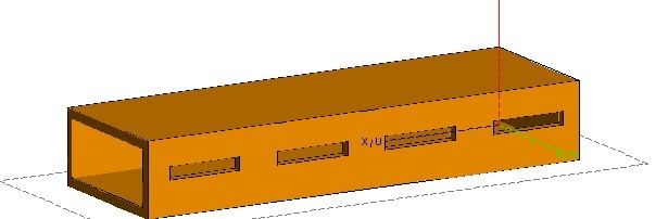
Figure 3.3– Model of the waveguide with 4slots.
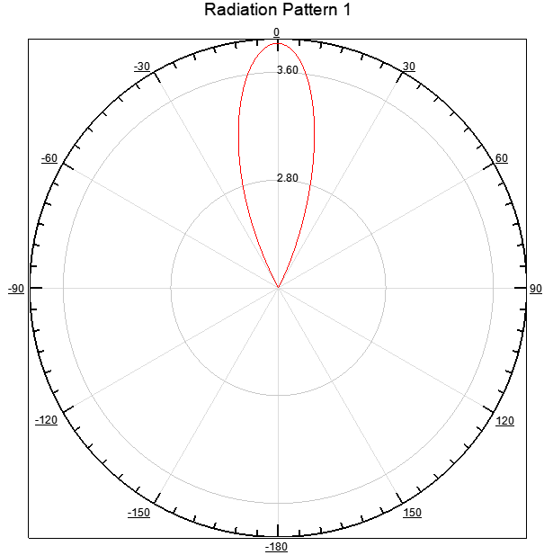
Figure 3.4 – Directional diagram of the waveguide-slit PHAR with 4 slits.
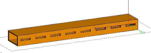
Figure 3.5– Model of the waveguide with 8slots.
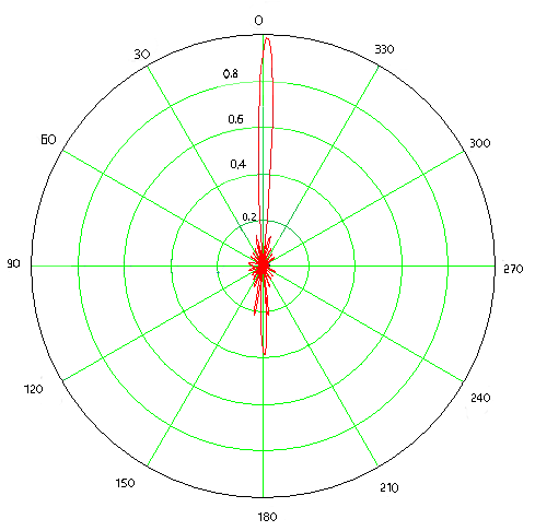
Figure 3.6 – Directional diagram of the waveguide-slit PHAR with 8 slits.
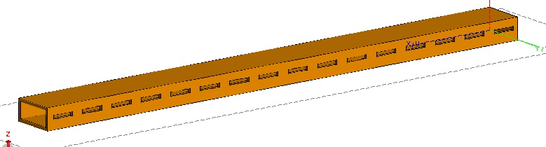
Figure 3.7– Model of the waveguide with 16 slots.
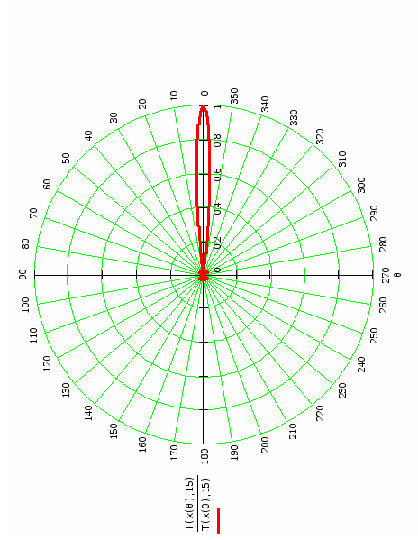
Figure 3.8 – Directional diagram of the waveguide-slit PHAR with 16slits.
Conclusion
During performance of the given research features of propagation of radio waves in atmosphere of the Earth, in particular waves of a microwave range have been studied. Use of radio waves of microwave range is the main, defining feature of the waveguide-slot antennas. This is due to the fact that the dimensions of the waveguide are calculated based on the wavelength, and, therefore, the smaller the wavelength, the smaller the dimensions of the waveguide used, as well as the fact that VHF have the following properties: a large frequency capacity, the practical absence of atmospheric and industrial interference, small diffraction (enveloping) capacity and the possibility of creating antenna devices narrowband radiation and reception of electromagnetic waves.
Modeling of the waveguide-slot PHAR was carried out in the FEKO software product, designed for the design and electrodynamic modeling of three-dimensional microwave devices, based on several calculation methods. Having analyzed the obtained directional diagrams of waveguide-slot PHARs with 2, 4, 8 and 16 slits, it can be concluded that a consecutive increase in the number of slits has a significant effect on the antenna parameters. This is reflected in the fact that there is a narrowing of the DN and an increase in the antenna gain at the operating frequency.
References
- Kalinin, A. I. Radio-wave propagation and the work of radio lines / A. I. Kalinin, E. L. Cherenkova. - Moscow: Communications, 1971. - – 440.
- Grudinskaya, G.P. Radio-wave propagation / G.P. Grudinskaya. - Moscow: Higher School, 1967. - – 244.
- Kalashnikov, A. M. Oscillating Systems: Textbook / A. M. Kalashnikov, Y. V. Stepuk. - Moscow: Voenizdat, 1972. - – 376.
- Handbook on radio-relay communication / N. N. Kamensky [et al] ; edited by S. V. Brodich. - Moscow : Radio and Communications, 1981. - – 416.
- Mordukhovich, L.G. Radio communication systems. Course Design: textbook for universities / L. G. Mordukhovich, A. P. Stepanov. - Moscow: Radio and Communications, 1987. - – 192.
- Radio relay and satellite transmission systems : textbook for universities / A. S. Nemirovsky, O. S. Danilovich [and others] ; ed. by A. S. Nemirovsky . - М. Radio and Communications, 1986. - – 392.
- Lobach, V. S. Digital microwave communication systems: textbook on course design for universities / V. S. Lobach. - SPb. SPbGUT, 1998. - – 23.
- Goren S. CHESMIN: a heuristic for state reduction in incompletely specified finite state machines / S. Goren, F. Ferguson // Proceedings of the Conference on Design, Automation and Test in Europe. – 2002. – pp. 248-254.