
Abstract on the topic of the final work
Content
- Introduction
- Relevance of the topic
- Purpose and objectives of the study, planned results
- Overview of methods and tools for measuring fluid flow in a large-diameter pressure pipeline
- 1. Classification of flow measuring instruments in pipelines
- 1.1 Variable differential pressure flow meters
- 1.2 Venturi Tube
- 1.3 Turbine flow meter
- 1.4 Vortex flow meter
- 1.5 Electromagnetic flow meter
- 1.6 Pitot–Prandtl Tube
- 1.7 Flow meters with hydrometric turntables
- 1.8 Flow meters with local speed MHD converters
- Conclusions
- Literature
Introduction
To preserve such an important life-support resource as water, it is necessary to widely use devices for monitoring and recording its consumption – flow meters. Without flow meters, it is impossible to ensure the normal functioning of not only public utilities, but also the operation of industrial and agricultural enterprises. They are necessary for accounting for substances transported through pipes and consumed by various objects. Without the use of flow meters, it is difficult not only to keep records of resource consumption and ensure its savings, but also difficult to control leaks and exclude its losses.
Relevance of the topic
The relevance of the topic of the master's thesis is due to the need to introduce modern electronic systems for centralized measurement and accounting of drinking water consumption in large-diameter pressure (filled) pipelines at water supply points in large cities. The flow rate of droplet liquids in such pipelines is usually determined by an indirect method, based on the results of measurements of the cross – sectional area of the pipe and the speed at the flow point of this section (using the area-speed
method). Currently, to measure the flow of liquid in a fully filled pipeline, devices based on the use of an electromagnetic (magnetohydrodynamic - MHD) method for measuring flow or velocity are most often used. The method allows you to create inexpensive and reliable devices characterized by high metrological and operational characteristics, high stability of readings and their independence from the physical and chemical properties of the working fluid, the ability to transmit information about the value of the measured flow rate (speed) in the form of an electrical signal over long distances without loss or distortion.
Purpose and objectives of the study, planned results
The purpose of the dissertation is to study and substantiate the structure of a drinking water flow meter for large-diameter pressure pipelines with high operational and metrological characteristics.
To achieve this goal in the work:
• analysis of modern methods, methods and means of measuring the flow of liquid in pressure (filled) pipelines of large diameter is performed;
• an analytical review of modern methods and tools for measuring the local flow rate of droplet liquids in a circular pipeline is performed;
• a mathematical model of the MHD velocity Converter is obtained, which establishes the connection of the output signal of the Converter with the measured component of the velocity vector of the liquid flow;
• analysis of electrochemical processes occurring at the interface < q>liquid-working surface of the sensitive electrode MHD-speed converters is performed;
• study of the features of the processes of forming the output signals of MHD speed (and flow) converters when using different magnetic fields in them is carried out;
• taking into account the results of the research, the paper synthesizes a structural diagram of a drinking water flow meter for large-diameter pressure pipelines.
Overview of methods and tools for measuring fluid flow in a large-diameter pressure pipeline
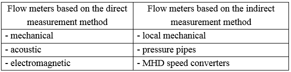
All flow measurement tools are divided into two classes according to the measurement method: direct flow measurement and indirect flow measurement. Devices based on the first method directly measure the flow of liquid in the pipeline [2]. Devices that implement the method of indirect flow measurement using the speed-area
method determine the flow rate of the liquid in the pipeline by the flow rate at one point of the pipeline cross-section (the average speed point) and its area [1,6,7]. In the latter case, flow measurement is based on the laws of turbulent fluid flow in the pipe, according to which the local flow rate V
at a point located at a distance [(0.242 ± 0.013) × R] from the inner surface of the pipe is equal to the average fluid velocity in this section – V = Vsr, which means – is proportional to its flow rate:

where Q – is the volume flow rate of the liquid; Vsr – is the average velocity of the liquid;
S – the cross-sectional area of the pipe.
1. Classification of flow measuring instruments in pipelines
1.1 Variable differential pressure flow meters
The diagram of the variable differential pressure flow meter is shown in Fig1.1
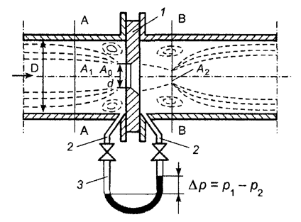
Figura1.1 – Flow meter diagram for variable differential pressure
For such a flow meter, a diaphragm installed in the pipeline on the path of liquid movement creates a pressure drop, which can be measured to determine the volume flow rate [2].

where α – coefficient that takes into account the compression of the flow and the velocity profile in the flow,
ε – coefficient that takes into account the change in the flow density in the tapering device,
F – the cross-sectional area of the pipeline,
ρ – liquid density,
ΔР – the measured pressure differential.
These flow measurement tools are widely used in industrial practice, which is explained by the simplicity of their design, and most importantly-the possibility of water – free calibration (verification, calibration). However, despite the wide variety of narrowing devices and specially designed designs, high accuracy of flow measurement using these measuring instruments can not be achieved
1.2 Venturi Tube
Venturi pipes (and nozzles) (figure 1.2) are more resistant to wear and allow passage of mechanical impurities. However, the measurement accuracy of these measuring instruments is significantly affected by the condition of the pipeline (frequent cleaning of pipes is necessary) and the length of the straight section of the pipeline before and after the transmitter.
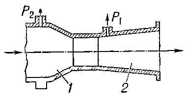
Figure1.2 – Diagram of a Venturi tube
Venturi pipes (and nozzles) have a number of advantages over diaphragms: lower hydraulic resistances, greater stability of readings, a wider measurement range, etc. But they are practically not used on pipelines of medium and large diameters, since the weight of a large-diameter Venturi pipe can reach several tons. This significantly complicates their installation, increases the complexity and cost of manufacturing.
1.3 ТTurbine flow meter
A characteristic feature of the design of these measuring instruments (Fig. 1.3) is the presence of a rotating element – a turbine, the rotation speed of which is directly proportional to the volume flow of the liquid [7].
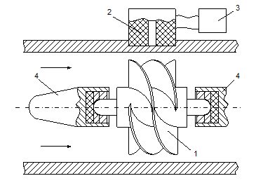
Figure 1.3 – Turbine flow meter diagram
The turbine flow meter consists of three main elements: a turbine primary Converter 1, a secondary Converter 2, and a counting system (recorder) 3. the Turbine Converter is an axial vane turbine rotating in bearings 4. the Flow of the measured medium, acting on the inclined turbine blades, gives it a rotational movement with an angular velocity ω proportional to the flow of the measured medium Q.
Advantages of turbine flow meters: simplicity of design; high sensitivity; wide dynamic range of measurements; the ability to measure small flow rates; low inertia and, as a result, small dynamic errors when measuring instantaneous flow values; linear dependence of their output electrical signal on the measured flow rate (speed) in the normalized measurement range.
Main disadvantages: the need for individual calibration; the impact of changes in viscosity and hydrodynamic parameters of the flow readings; the presence of supports, wear in operation, which leads to lower accuracy and requiring frequent calibration.
1.4 Vortex flow meter
The essence of the method is to create a stable vortex structure in the flow of a moving fluid (figure 1.4), the excitation of which is achieved by twisting the flow or by flowing around a fixed body of a special shape. There are several types of vortex flowmeters [2], but the final criterion for any design is the fluid pressure pulsations, which are characterized by the Reynolds number Re , which is the ratio of inertia forces to viscous friction forces in the flow, and the Strouhal number Sh=f·d/V, which determines periodic processes associated with fluid movement.
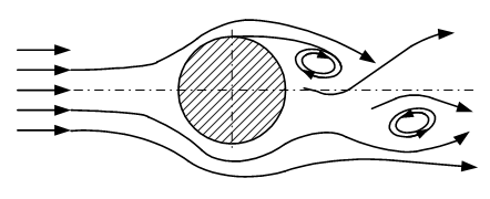
Figure 1.4 – Diagram of a vortex flow meter
The static characteristic of the conversion of vortex flowmeters has the following form:

where V – flow rate;
D – pipeline diameter;
ν – kinematic viscosity of the measured liquid;
f – the frequency of fluid pressure pulsations, as a result of periodic disruption of vortices;
d – the diameter of the body that causes periodic disruptions of vortices.
Advantages of vortex flowmeters: linear conversion characteristic, high accuracy (error within 0.5%), easy conversion, no moving parts, low inertia, frequency output signal. However, such flow meters with large pipeline diameters (over 250-300 mm) operate in the low-frequency region and do not provide stable vortex formation [2]. The disadvantages of vortex flow meters also include sensitivity to contamination of the measured medium.
1.5 Electromagnetic flow meter
Promising tools for measuring the flow of liquids with ionic conductivity (conductors of the second kind, to which drinking water belongs) include electromagnetic (magnetohydrodynamic) converters, the principle of operation of which is based on the fundamental law of electrodynamics-the phenomenon of electromagnetic induction. In accordance with it in a conductive medium moving in a magnetic field, induced electric field, the tension of E
is proportional to the induction value В
of the magnetic field and the speed of flow V
and does not depend on the physical properties of the medium (conductivity, temperature, viscosity, etc.). The directional electric field vector perpendicular to the velocity vector of the movement of the conductor and the induction vector of a magnetic field applied [4]:
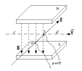
Figure 1.5 – To explain the principle of operation of the electromagnetic flow Converter (speed)
The electric field induced in a liquid is potentially [2]:

where φ – is the potential of the electric field induced in the liquid
An electromagnetic conduction flow meter consists of (Fig. 1.6): a) a measuring section of the pipeline 1 made of non-magnetic material and having an internal insulating coating; b) a magnetic system 2 located outside the pipeline; C) two electrodes 3 (E1 and E2) designed to remove the potential difference induced in the liquid, and located at the ends of the pipe diameter perpendicular to the direction of movement of the liquid and the direction of the magnetic field lines, flush with the inner surface of the pipeline.
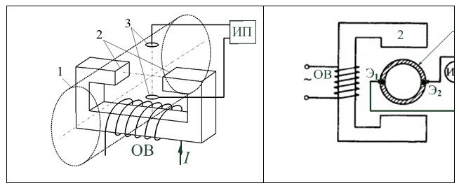
Figure 1.6 – Electromagnetic flow meter design
An important advantage of electromagnetic flow meters is the absence of protruding or moving parts in the flow. Therefore, such devices do not violate the hydrodynamic structure of the flow and do not create additional hydraulic resistance. They do not require constant maintenance and can be successfully used for measuring the flow rate of liquids with impurities and suspensions, acids, alkalis, and many other polluted and aggressive media [2 –4], but for larger diameter pipelines it is technically difficult to form a uniform magnetic field of the required strength in the entire pipe section by means of a magnetic system located on the pipeline surface, due to the significant weight and dimensions of the magnetic system.
1.6 Pitot–Prandtl Tube
1.6 Pitot–Prandtl Tube creates a pressure drop depending on the flow rate that exists at the installation site. Currently, Pitot – Prandtl tubes of various modifications are known, but their use for measuring local velocity in liquid flows is mainly limited to laboratory studies. This is primarily due to the requirement of the absence of suspensions, impurities and precipitation in the measured liquid. Pitot – Prandtl tubes have a number of disadvantages, the main of which are: a) high inertia; b) low sensitivity (about 15-20 cm/s); non-linearity of the calibration characteristic, especially affecting when measuring low speeds of less than (3-5) m/s [5].
1.7 Flow meters with hydrometric turntables
The main element of such flow meters is a hydrometric turntable. It is usually of the axial type. The speed of rotation of the turntable is proportional to the flow rate at the point where the center of the turntable is located. In practice, flow meters with hydrometric turntables measure the flow rate at the cross-sectional point of the pipeline.
Flowmeters with hydrometric turntables for pipelines of large diameters are characterized by insignificant pressure losses, which are caused by placing the primary speed measuring Converter (turntables) in the flow under study. This is their dignity.
The disadvantages of such devices include the presence of moving parts of the flow meter in the pipeline and, as a result, the need to have a fairly complex system for their lubrication. In comparison with pressure pipes hydrometric turntables have large dimensions [2].
1.8 Flow meters with local speed MHD converters
Disadvantages of electromagnetic flowmeters based on the direct measurement method, associated with large dimensions, iron and copper consumption, as well as power supply, force us to abandon such measuring instruments and use electromagnetic speed converters with a magnetic field localized in the area of installation of sensitive electrodes. Such electromagnetic flow meters with a local magnetic field introduced into the flow are simpler and cheaper, and their advantage increases with increasing pipeline diameter. The magnetic field in the area of the sensitive electrodes of the Converter is created by a miniature coil powered by alternating current. [3,4]. In addition, various types of magnetic field concentrators located directly in the vicinity of the electrodes can be used to increase the sensitivity of the flow meter.
The prospects of electromagnetic flow meters with a local magnetic field are due to the fact that they have small dimensions, minimally disturb the flow, are technological, durable, have low metal consumption and low energy consumption, are easily installed by standard inputs in continuous pipelines, etc. [2,7]. The high performance of such flow meters rightfully puts them among the most promising devices for measuring the flow of water in pipelines of large diameters.
Conclusions
1.Currently, there are no reliable meters that provide reliable information about the flow of liquid media in pipelines of large diameters and meet all the requirements for modern flow measurement tools.
2.Flow measurement tools can be divided into two classes: direct flow measurement and indirect flow measurement. Devices implementing the method of direct measurement, directly measure the fluid flow in the piping; devices implementing a method of indirect measurement to determine the fluid flow in the conduit velocity at one point of the cross section of the pipeline (the point of average velocity) and its area.
3.Flow meters based on the method of determining the flow rate from the flow rate at one point of the pipeline cross-section and its area meet the most complete task of measuring the flow rate of liquid media in filled pipelines of large diameters.
Literature
- ГОСТ 8.361-79. Методика выполнения измерений по скорости в одной точке сечения трубы. Введ. 01.07.90. - Изд-во стандартов, 1979. -14с.
- Кремлевский П.П. Расходомеры и счетчики количества вещества: Справочник. - Кн. 2 – СПб.: Политехника, 2004. – 412 с.
- Корсунский Л.М. Электромагнитные гидрометрические приборы. – М.: Стандартгиз, 1964. – 180с.
- Шерклиф Дж. Теория электромагнитного измерения расхода: Пер. с. англ. – М.: Мир, 1965. – 268 с.
- Зори А.А. Методы, средства, системы измерения и контроля параметров водных сред: монография / А.А. Зори, В.Д. Коренев, М.Г. Хламов – Донецк: РИА ДонГТУ, 2000. – 388 с.
- ГОСТ 8.439-81. Методика выполнения измерений методом площадь-скорость. Введ. 23.09.81. – Изд-во стандартов, 1982. – 51 с.
- [Electronic resource]. – Access mode: https://elib.gstu.by/bitstream....