
Abstract
Contents
- Introduction
- 1. Relevance of the topic
- 1.1 Hydraulic characteristics of closed mines in Donetsk
- 1.2 General characteristics of a submersible drainage system
- 2. Formalization of the control object
- 3. Purpose and functions of ACS
- 4. Basic user requirements for the developed ACS
- 5. Analysis of existing drainage automation systems
- Conclusions
- References
Introduction
Currently, the problem of closing coal mines is very acute – both economically ineffective and those that have exhausted all coal reserves. However, it is not always possible to start the liquidation of a mine immediately with its physical closure. Groundwater from the abandoned mine, after its flooding, can migrate to neighboring mines (if they are associated with the abandoned mining operations), or come out to the surface. The drainage complexes existing at the neighboring operating mines, as a rule, are not able to accept the significantly increased inflow of water. In order not to flood the existing mines, it is necessary to reconstruct their drainage complexes or build new drainages.
The operation of drainage complexes of closing mines has its own characteristics and differences that must be taken into account when automating this technological process.
Thus, the purpose of development is – increasing the efficiency of the submersible drainage system through the development of an automatic control system, which will extend the service life of technological equipment, improve reliability and safety, and also reduce operating costs for the process of drainage of liquidated coal mines.
Achieving this goal is possible due to a deep study of this control object, the development and implementation of the necessary control algorithms using a modern element base – programmable logic controllers and specialized telecommunication networks for the interaction of ACS elements.
1. Relevance of the topic
1.1 Hydraulic characteristics of closed mines in Donetsk
Former mine No.9 «Capital» located on the territory of the Proletarsky district of the city of Donetsk, currently the mine has been liquidated.
Unit is located on the former main industrial site of the mine No.9 «Capital». The nearest industrial facilities are the mines of the former «Krasnaya Zvezda» mine administration.
The average inflow of water according to the study and survey of mines in Budenovskiy and Proletarskiy districts of Donetsk amounted to mine No.6 «Krasnaya Zvezda» – 260 m³/h, No.9 «Capital» – 340 m³/h.
On the basis of a hydro–forecast regarding the possible activation of the process of displacement of rocks and the earth's surface, the following option was adopted to ensure the hydrogeological and ecological safety of the surface.
1.2 General characteristics of a submersible drainage system
Expected mine water production No.9 «Capital» – 340m³/h. Geodetic discharge head – 176.5 m. Technological scheme of a submersible drainage system of a mine No.9 «Capital» is shown in Fig. 1.
The mark of the upper working level +10 m, the lower working level +9 m, the mark of the critical emergency level +30 m, the minimum water level in the catchment area is 6 m (based on the conditions of stable non–cavitation operation of submersible pumping units ANPSH 375–240 [1]).
According to the requirements «Safety rules in coal mines» [2] to pump out the above inflow, three submersible pumping units of the ANPSH type are installed in the skip shaft 375–240: two units – workers, one – standby, pumping is carried out through 3m pressure pipelines with a diameter of 273 x 11.4 suspended in the shaft (Fig.1).
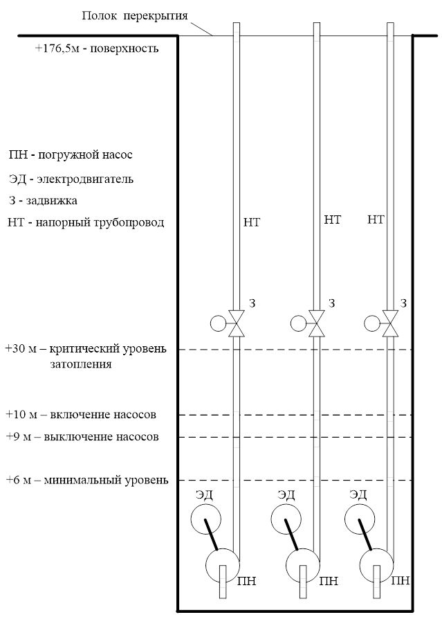
Picture 1 – Technological scheme of the submersible drainage system of the mine
The pump is started and stopped in accordance with the operating instructions for the submersible pump unit of the plant.–manufacturer. In working position, the pump unit is completely submerged in water. To protect the pump unit from cavitation in the event of an unacceptable decrease in the water level, the minimum water level in the sump is set at +6 m.Thus, taking into account all the features and restrictions, the level mark +10 m corresponds to the upper level, upon reaching which the submersible is started pumping unit; elevation +9 m – the lower level, upon reaching which the submersible pumping unit stops; +30 m – emergency, critical level, upon reaching which the second submersible pumping unit is launched; elevation +6 m – the minimum permissible lower water level in the sump required for stable, cavitation–free operation of ANPSh submersible pumping units 375–240 (Fig.1)
2. Formalization of the control object
The efficiency of submersible drainage is influenced by a number of parameters of a submersible pumping unit, which determine its current state. [3–4]: Q(t) – submersible pumping unit feed; H(t) – head (pressure) of a submersible pumping unit; HВ(t) – vacuum suction head (back pressure at the inlet to the pump unit); HГ – geodetic discharge head; η – efficiency of the pumping unit; n – pump shaft speed; dВ – suction pipe diameter; dН – diameter of the discharge line; lВ – suction pipe length; lН – delivery line length; aВ – hydraulic resistance of the suction pipeline; aН – hydraulic resistance of the discharge pipeline; hУ(t) – water level in a catchment; QП(t) – hourly inflow into mines.
The above variables and parameters of a submersible pumping unit are interconnected through the equations of the pressure characteristics of the pump and the discharge pipeline [3–4]. The equation of the pressure characteristic of a submersible centrifugal pumping unit is written in the following form: [5–6]:
Where H0 – pump head created when the valve is closed; Q – supply (capacity) of the pump; A, B, – constant coefficients for the selected type of pump (determined by reference).
The equation of the pressure characteristic of the injection pipeline, as a rule, can be represented as [3–4]:
Where HГ – the geometrical height of water rise (for the object under consideration is equal to the geodetic injection height – 176.5 m); ΔHФ – actual head loss in the pipeline.
The operating mode of a submersible pumping unit is determined by the joint operation of the pumping unit and the discharge pipeline, and it can be determined by an analytical or graphical solution to the system of equations for the pressure characteristic of the pumping unit and the pressure characteristic of the discharge pipeline. The point of intersection of characteristics (point A) (Fig. 2) determines the operating mode of the submersible pumping unit. It also shows the curve of the pump efficiency and the permissible vacuum head suction НВ.
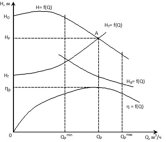
Figure 2 – Characteristics of a submersible pumping unit
Рthe operating mode of the centrifugal pumping unit must satisfy the condition of cavitation–free operation HB < HBp. In the submersible drainage system under consideration, the stable, cavitation–free operation of the pumping unit depends solely on the value of the water level in the drainage tank hУ and is provided by its (level) required maintenance.
For the considered control object – a submersible drainage system, the main disturbance that maximally affects and determines the mode of its operation is the hourly inflow of the mine QП. Taking into account the above analysis of the features of a submersible drainage system, its generalized diagram as a control object was obtained (Fig. 3)
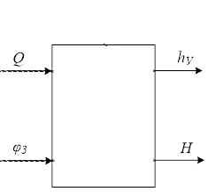
Figure 3 – Generalized diagram of a submersible drainage system as a control object (animation: 30 frames, 70 kilobytes)
3. Purpose and functions of ACS
Цspruce of the developed ACS – increasing the efficiency of a submersible drainage system by developing an automatic control system, which will extend the service life of technological equipment, increase reliability and safety, and also reduce operating costs for the process of drainage of liquidated coal mines.
To achieve this goal, you must:
- to receive information about the main parameters characterizing the submersible drainage system: about the water level in the drainage tank, about the flow rate of each pumping unit, about the head (pressure) at the outlet of each pumping unit;
- implement the required control and management algorithms based on the information received about the parameters of the submersible drainage system;
- to carry out the issuance of the received control actions to the control object – a submersible drainage system through the corresponding actuators of the ACS;
- perform the required interaction with the operator through human elements–machine interface.
The developed automatic control system for a submersible drainage system of a coal mine should perform the following functions:
- collection, processing, distribution of information about the current state of elements of the submersible drainage system;
- automatic control of the pumping unit and the valve on the discharge pipeline;
- information and computational properties that implement algorithms for calculating control actions using the accumulation and necessary averaging of information;
- implementation of algorithms for service functions.
- quality indicators of control of parameters of a submersible drainage system should be no worse than those of existing similar systems and comply with the requirements of regulatory documents
- the accuracy of measurements and calculations in the developed ACS with a submersible drainage system should be worse than that of existing analogues.
- the recoverability and maintainability in the developed automatic control system of a submersible drainage system must be no worse than that of existing systems and comply with the requirements of regulatory documents.
- electrical equipment, automation elements and devices, computer facilities must have appropriate protection classes;
- elements of the automatic control system (sensors, actuators, regulating bodies, control devices) must have the required level of explosion protection.
- the flow rate of the pump unit is not controlled for «work on inflow»;
- lack of control function of the drainage system in dynamic modes – smooth start and stop with a closed valve;
- there is no function of smooth opening and closing of the valve to exclude hydraulic shocks and surges in pressure;
- lack of functions for monitoring the main technological parameters – the flow and pressure of the pumping unit;
- Указания по монтажу и применению в проектах систем шахтного водоотлива агрегатов насосных погружных шахтных АНПШ. Инструкция по эксплуатации АЭТА.062313.005.375.250ТО. ОАО Завод «Молот», 2010.– 40 с
- Правила безопасности в угольных шахтах. Киев: ООО «ЛИГА ЗАКОН», 2010.– 185 с.
- Гейер В.Г., Тимошенко Г.М. Шахтные вентиляторные и водоотливные установки. М.: Недра, 1987.– 270 с.
- Попов, В.М. Шахтные насосы (теория, расчет и эксплуатация). / В.М.Попов – М.: Недра, 1993. – 224 с.
- Автоматизация процессов подземных горных работ. // Под общей ред. Иванова А.А. – Киев; Донецк: Вища шк., 1987. – 327 с.
- Grout I. Digital systems design with FPGAs / I. Grout. – Elsevier, 2008. – 724 pp.
- Zeidman B. Designing with FPGAs and CPLDs / B. Zeidman. – Elsevier, 2002. – 224 pp.
- Баранов С.И. Синтез микропрограммных автоматов (граф–схемы и автоматы) / С.И. Баранов. – Л.: Энергия, 1979. – 232 с.
- Глушков В.М. Синтез цифровых автоматов / В.М. Глушков. – М.: Государственное издательство физико–математической литературы, 1962. – 476 с.
- Компания ДЭП [Электронный ресурс]: офиц. сайт. – Электрон. дан. – Донецк, [2019]. – Режим доступа: http://dep.ru.
- ООО
Научно–производственное предприятие РУДПРОМАВТОМАТИКА
[Электронный ресурс]: офиц. сайт. – Электрон. дан. – Кривой Рог, [2019]. – Режим доступа: http://www.rpa.ua/. - Бессараб, В. И. Управление шахтной водоотливной установкой в аварийных и аномальных режимах работы / В. И. Бессараб, Р. В. Федюн, В. А. Попов // Научные труды Донецкого национального технического университета. Серия:
Вычислительная техника и автоматизация
. Выпуск 106. – Донецк: ДонНТУ, 2006. – 220 с. – С. 26–33. - Бойко, Н. Г. Рудничные (шахтные) водоотливные и вентиляторные установки: конспект / Н. Г. Бойко; Н. Г. Бойко; ДонНТУ, Каф.
Энергомеханические системы
. – Донецк, 2009. – 168 с. - Карелин, В. Я. Кавитационные явления в центробежных и осевых насосах – Москва: Недра, 1975 – 353 с.
- Автоматизация сложных электромеханических объектов энергоемких производств: учебное пособие для вузов / К. Н. Маренич [и др.]; К. Н. Маренич, С. В. Дубинин, Э. К. Никулин и др.; ГВУЗ
ДонНТУ
. – Донецк: ОООТехнопарк ДонГТУ
, 2015. – 237 с.УНИТЕХ
1) management functions:
2) protection functions:
3) information functions:
4. Basic user requirements for the developed ACS
Functionality requirements:
Performance requirements:
Reliability requirements:
Safety requirements:
5. Analysis of existing drainage automation systems
All existing systems for automatic control of drainage have a common drawback – they do not take into account the dynamic properties of the components of the drainage installation and the dynamic processes occurring in them.[6–7].
The analysis of the functional capabilities of the KUPNA device showed that the main protection and control functions relate to the drive electric motor of the pump (control of the active power of the electric motor, control of the electric motor current, the value of the power factor of the installation, protection and control of the parameters of the electric motor, control of the insulation resistance of the system «cable–engine»).The pumping unit itself includes the function of starting and stopping the pump, depending on the water level in the sump.
The KUPNA device does not perform the following control and monitoring functions of the pump unit:
Conclusion
The analysis of the submersible drainage system of a coal mine as an object of automatic control is carried out.
Based on the results of the analysis performed, the control object – a submersible drainage system was formalized, the requirements for the developed automatic control system were formulated for the functions of monitoring, control and protection, and the user's requirements for the ACS were set.[9]
Existing automatic control systems for coal mine drainage units, including the KUPNA–700SH (V) control system developed for submersible pumping units, do not perform all the necessary functions for the control, monitoring and protection of the considered control object – a submersible drainage unit. Therefore, the development of an automatic control system for a submersible drainage system is currently relevant in the context of a large number of liquidated coal mines.