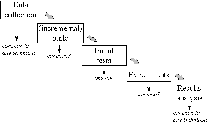
Figure 1. Overview of the modelling process
This paper was originally presented at the 2nd DYCOMANS workshop on "Management and Control : Tools in Action" in the Algarve, Portugal. 15th - 17th May 1996, pp. 367-376. Reproduced with permission. (DYCOMANS is a European Community Copernicus Network)
The original paper and the overhead slides are available (as Microsoft Word and Microsoft Powerpoint files respectively) at a small "fee". This "fee" is to supply me with one good aspect and one bad aspect of this web page when you request the files. Contact Peter Ball for copies.
Discrete event simulation is one way of building up models to observe the time based (or dynamic) behaviour of a system. There are formal methods for building simulation models and ensuring that they are credible. During the experimental phase the models are executed (run over time) in order to generate results. The results can then be used to provide insight into a system and a basis to make decisions on.
The paper will firstly describe a number of application areas before introducing some of the elementary principles of discrete event simulation. These basic principles are then brought together via an illustrated hand simulation that leads the reader through the basic steps in a discrete event simulation.
The paper goes on to discuss more general issues of simulation that are of wider interest, such as the power of object-oriented simulation systems such as Simple++ and the use of continuous simulation for the process industries and process plant.
The paper concludes with some observations on current and future issues in this area of simulation. A bibliography is provided and this is seen as essential support for the concepts described.
One area where simulation is commonly used is in the area of developing new systems, particularly those that involve a high capital investment. For example, simulation can be used to test the performance of personal computer (PC) assembly lines to ascertain the throughput possible, the level of utilisation of operators and any potential problems. Further investigations can be carried out to assess the best position for work-in-progress (WIP) stores and the levels to be used.
For systems that already exist, simulation can be used to test for minor design changes or to look at the control policies. For example, for bottling lines (e.g. for Scottish malt whisky!) the rules used to control the flow of bottles can be investigated as well as the effects of minor breakdowns. It will be shown later that this is probably not the most ideal application of discrete event simulation and that this raises the possibility of using either ?continuous? simulation or combining continuous and discrete event simulation.
The above applications are essentially flow lines. Other application areas for simulation include job shops in which small batch manufacture takes place. Whilst simulation is certainly suitable for this area the instances of its use are relatively low, perhaps due to the inherent complexity of the manufacturing systems!
Other application areas include service systems such as banks and airports. The classic problem modelled by discrete event simulation software is to determine the number of tellers required to serve customers. In airports modelling luggage handling is common. Additionally with the popularity of a re-design technique known as Business Process Reengineering (BPR) there are a number of simulation packages that offer functionality assisting with a BPR exercise.
There is a wide potential area for using discrete event simulation. Unfortunately it is predominately used where the risks are high, particularly if capital investment is high. This tends to reflect the relative difficulty of using older, less user friendly versions of simulation software rather than the potential benefits that the technique offers.

Whichever software or technique is used for modelling there are a number of important considerations to be made:
Inside the software or model will be a number of important concepts, namely entities and logic statements.
Entities are the tangible elements found in the real world, e.g. for manufacturing these could be machines or trucks. The entities may be either temporary (e.g. parts that pass through the model) or permanent (e.g. machines that remain in the model). The concepts of temporary and permanent are useful aids to understanding the overall objectives of using simulation, usually to observe the behaviour of the temporary entities passing through the permanent ones.
Logical relationships link the different entities together, e.g. that a machine entity will process a part entity. The logical relationships are the key part of the simulation model; they define the overall behaviour of the model. Each logical statement (e.g. "start machine if parts are waiting") is simple but the quantity and variety and the fact that they are widely dispersed throughout the model give rise to the complexity.
Another key part of any simulation system is the simulation executive. The executive is responsible for controlling the time advance. A central clock is used to keep track of time. The executive will control the logical relationships between the entities and advance the clock to the new time. The process is illustrated in Figure 2. The simulation executive is central to providing the dynamic, time based behaviour of the model. Whilst the clock and executive are key parts of a simulation system they are very easy to implement and are extremely simple in behaviour.
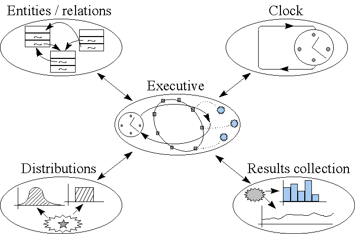
Two other elements that are vital to any simulation system are the random number generators and the results collation and analysis. The random number generators are used to provide stochastic behaviour typical of the real world. For example, machine scrap rates will rarely be fixed but will vary between certain ranges hence the scrap rate of a machine should be determined by a random distribution (probably a normal distribution).
The results collation and display provides the user a means of utilising the simulation tool to provide meaningful analysis of the new or proposed system. Simulation tools will typically display tabulated raw results and possess some graphing capabilities.
There are two basic approaches for controlling the time advance:
With next event the model is advanced to the time of the next significant event. Hence if nothing is going to happen for the next 3 minutes the executive will move the model forward 3 minutes in one go. The nature of the jumping between significant points in time means that in most cases the next event mechanism is more efficient and allows models to be evaluated more quickly.
There is a word of warning when using next event simulation software. Simulation software invariably have graphical displays to show the user the changing status of machines (running, idle, etc.) and the movement of parts. Because the software jumps between significant points in time the jumps may be uneven with many jumps separated only by 5 seconds of simulated time followed by one or two jumps of 4 minutes say. The effect is that the series of snap shots shown by the graphical displays can be misleading and machines may appear broken down for long periods of time when in fact this is not the case. The situation is analogous to watching a video that is continually being speeded up and slowed down.
The approaches are illustrated in Figure 3 are :

The event approach describes an event as an instantaneous change and such events are usually paired, e.g. start of machine loading, end of machine loading, etc. Activities describe a duration, e.g. machine loading, and are therefore very similar to pairs of events. The process approach joins collections of events or activities together to describe the life cycle of an entity, in this case a machine.
The event approach is easy to understand and computationally efficient but is more difficult to implement than the activity approach. On the other hand whilst activity approach is relatively easy to understand it suffers from poor execution efficiency. The process is less common and requires more planning to implement properly though is generally thought to be efficient.
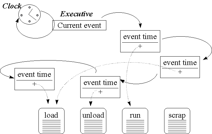
The executive is responsible for ordering the events. The executive removes the first event from the list and executes the relevant model logic. Any new events that occur as a result are inserted on the list at the appropriate point (e.g. a machine start load event would generate a machine end load event scheduled for several seconds time). The cycle is then repeated.
Each event on the event list has two key data items. The first item is the time of the event which allows it to be ordered on the event list. The second item is the reference to the model logic that needs to be executed. This allows the executive to execute the correct logic at the correct time. Note that more than one event may reference the same model logic, this means that the same logic is used many times during the life of the simulation run.
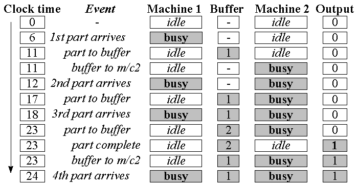
The model starts from the common starting point know as ?empty and idle?; the all entities are idle and there are no parts in the system.
The next most significant time is 6 when the first part arrives. The executive jumps straight to this time. When the first part arrives the first machine starts processing it. At time 11 (5 later) the executive will cause the first machine to place its processed part in the buffer. Immediately the second machine takes the part and starts processing it. Note that events may occur at the same time, as well as there being significant times between events.
The model unfolds over time with parts arriving, being processed on machine1 and placed in the buffer. As would be expected parts accumulate in the buffer since machine2 is slower.
For a graphical display the machines would be shown as icons changing colour when running. According to a graphical display it would appear that machine2 is busier than machine one. If the figures for the busy time are added up for each machine (machine1 : 16 -vs- machine2 : 13) it is apparent that machine1 was busier. This is one of problems noted before that can occur when the graphical displays of next event simulation are taken too literally.
Note that in a practical situation variations would be attached to many aspects of the model (cycle time variations, machine breakdowns, scrap, machine efficiency variations, etc.) and that the model would be simulated for significantly longer to be able to have confidence that the results are credible.
The Witness software, which grew from software to model Rover?s car production lines, allows the user to build up a model in three phases:
The display stage simply allows the user to position icons on a graphical display to illustrate the model. During the simulation the icons will change colour to reflect their state such as busy, idle, broken down, in repair, etc.
The detail is the most important and has direct influence on the behaviour of the overall model. Here rules are put in place to control the movement of parts and the rules governing the start and end of processing. The necessary data entry at this stage is shown in Figure 6.

The power of object oriented techniques lie in the ability to produce ?modular? code (known as classes) that can be "easily" modified and reused (Shewchuk & Chang, 1991). Libraries of the classes can be built up and used to create software such as simulation models. The ability to contain software complexity into classes and to be able to realistically represent entities from the real world in software make OO techniques ideally suited to simulation which is inherently complex.
There are few OO simulation packages available commercially but one such package founded on OO principles is Simple++. Simple++ provides a library of classes that can be used to create simulation models.
Note that the difference between traditional software design and that of object-oriented software is that way in which the data and mechanisms are structured. In traditional simulation software the data and the event routines are dispersed throughout the software. In the OO approach anything related to a single entity (both data and event routines) are bundled together to form a class (e.g. a machine). Objects (e.g. machine1, machine2, etc.) of the machine class can then be created.
One of the key advantages of Simple++ over other simulation packages is the ability to use the OO concepts to extend the functionality of the software. By taking the base functionality (e.g. transport) classes can be inherited to create a more dedicated classes (e.g. conveyor). Hence the general functionality of Simple++ such as "moving units" and "processors" can be inherited to provide manufacturing specific functionality. Furthermore the manufacturing functionality can be inherited to company specific functionality. See Figure 7.
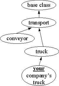
There are two important points to note here that illustrate the power of object-oriented simulation software. Firstly, the functionality developed is part of a library, not a model. Therefore the functionality is developed independently and used to build many different models quickly. Secondly functionality developed as a library can be exchanged with other users of Simple++ in other institutions. E.g. if one institution or company developed a class library for hot rolling mills this could be given to others to enable them to quickly develop their own models of their own particular rolling mills of interest.
The ability of many commercial simulation tools to allow both continuous and discrete gives rise to some potentially powerful modelling tools. Here some elements controlled by differential equations others by events. For example in a steel mill model there would be an event for heating of steel to start, with temperature rise determined by differential equations according to amount of power applied.
Taking the earlier application example of modelling bottling lines, continuous simulation techniques could be used to develop more computationally efficient models. For example, with conveyors transporting bottles instead of modelling individual bottles travelling along the conveyors, the conveyors could be modelled as continuous elements described by an input rate, output rate and volume stored.
Many systems have default control rules in place which the user then has the option of editing to suit the particular investigation. Whilst editing the rules is easy, the user must ascertain where they should be placed as well as have knowledge of their syntax. A simple example of the control rules for Witness are the push and pull rules described earlier. With the rules distributed throughout a model it is difficult to get an overview of the rough likely behaviour of a model.
In addition to this the ability to define standard manufacturing control rules, such as those required for Kanban (see Monden, 1981), are often poorly provided for; whilst such rules can developed from first principles it places demands on the ingenuity of users to create them.
There are a number of phases for checking a simulation model prior to experimental analysis:
A simulation run typically starts in the empty and idle state. The run is therefore characterised by a "run-in" phase followed by a "steady state" phase, see Figure 8. The run-in phase is generally ignored and is only used for investigating the effects of transient conditions such as starting up a new factory or performing radical changes within an existing facility.
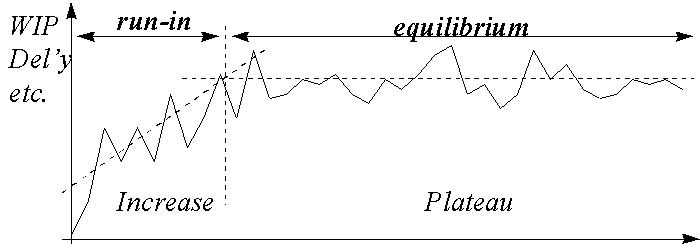
Typically the steady state phase is of greater interest. At this stage checks must be made to ensure no long term trends exist, such as continual build up of stock in the factory, that suggest the model (hence the real system) will be unstable and unworkable.
Generally what is know as multiple replication is performed. This is where the model is run several times. Each time the random number generators are set to provide different sequences of random numbers, e.g. the breakdown patterns of machines are different and the points at which material is scrapped is different. This allows confidence that the results being compiled represent the average and the range of conditions that are likely and therefore play down ?freak? or ?unusual? behaviour.
With the interesting demands for user-friendly software and the greater availability of software libraries for creating them simulation user-interfaces will become increasingly easier to use. There is an increase in the use of graphical displays in which icons are dragged from a library into the model. There is also a trend towards integration with other software, hence in many package data export facilities exist to enable the data to be easily moved, for example, to a spreadsheet.
As noted earlier the costs of simulation software are likely to fall. The increasing awareness of simulation and the increasing ease of use will open up simulation to a wider audience and could result in lower prices due to economies of scale. Also the advent of cheap packages such as SIMUL8 could cause prices to fall.
There may also be a change in the way simulation models are built. It is fair to say that the way in which discrete event simulation models are built is different to many other approaches to building models. There are, however, flow charting tools (e.g. ProcessCharter - see review) which have simulation capabilities embedded within them. Hence there is a change here towards embedding simulation into more traditional modelling tools thus requiring less of a conceptual jump for new users.
The initial part of the paper described some application areas before detailing the next event approach. Other relevant areas such as object-oriented simulation (the example being Simple++) were described.
The paper also discussed the issues surrounding experimentation with discrete event simulation. Many of the concepts such as verification, validation, steady state and multiple replication have much in common with the procedures used for other modelling techniques and their importance cannot be overstated.
The use of discrete event simulation for modelling manufacturing systems (and other systems) has shown benefits to many companies. The evidence for this is both anecdotal and from that presented in the engineering literature.
Kreutzer, W. 1986. Systems Simulation - Programming Styles & Languages. Addison-Wesley
Law, A.M. & Kelton, W.D. 1991. Simulation modeling and analysis. Singapore: McGraw-Hill Book Company.
Monden, Y. 1981. "A Special Report: Adaptable Kanban System Helps Toyota Maintain Just-In-Time Production." Industrial Engineer, May 1981: 29-46.
Shewchuk, J.P. & Chang, T.C. 1991. "An approach to object-oriented discrete event simulation of manufacturing systems." Proceedings Winter Simulation Conference, Phoenix, Arizona, USA: IEEE: 302-311.
Simulation Study Group. 1991. Simulation in UK Manufacturing Industry. The Management Consulting Group, University of Warwick Science Park, Coventry, CV4 7EZ, UK
Proceedings of the Winter Simulation Conference. This is US conference held each December addressing wide range of issues. It always has basic and advanced tutorials and papers on each of the commercial simulation software packages. Published by the IEEE.
Kreutzer, W. 1986. Systems Simulation - Programming Styles & Languages. Addison-Wesley. This book is useful for its in-depth descriptions of the event, activity and process simulation mechanisms. In particular there is a wealth of diagrams and useful program code to back them up.
Pidd, M. 1992. Computer Simulation in Management Science. Wiley. This is a popular book for teaching simulation to university students. It addresses a wide range of issues, explains the various simulation mechanisms and goes on to discuss systems dynamics.
Law, A.M. 1986. "Introduction to simulation ?". Industrial Engineering, May 1986, pp. 3-12. This paper is easily obtainable and gives an overview of discrete event simulation and the event mechanism.
Stuart Robinson. (1994) "Successful simulation : a practical approach to simulation projects." McGraw-Hill Book Company.
Industrial Engineering. This light weight engineering publication for members of the US IEEE. It is readily available in libraries. Whilst it covers a wide range of engineering issues there are regular articles on the application of simulation in industry.