![]()
|
|
M. RachidPower Electronics HandBookFuzzy Logic in Elecric DrivesSource: Rashid M. Power Electronics Handbook, © 2001, AcademicPress |
![]()
Over the years, we have increasingly been on the
search to understand the human ability to reason and make decisions, often in
the face of only partial knowledge. The ability to generalize from limited experience
into areas as yet unencoun-tered is one of the fascinating abilities of the
human mind. Traditionally, our attempt to understand the world and its functions
has been limited to finding mathematical models or equations for the systems
under study. This approach has proven extremely useful, particularly in an age
when very fast computers are available to most of us with only a minimum amount
of capital outlay. And even when these computers are not fast enough, many researchers
can gain access to supercomputers capable of giving numerical solutions
to multiorder differential equations that are capable of describing most of
the industrial processes.
This analytical enlightenment,
however, has come at the cost of realizing just how complex the world is. At
this point, we have come to realize that, no matter how simple the system is,
we can never hope to model it completely. So instead, we select suitable approximations
that give us answers that we think are sufficiently precise. Because our models
are incomplete, we are faced with one of the following choices:
1. Use the approximate model and introduce probabilistic representations to allow for the possible errors.
2. Seek to develop an increasingly complex model in the hope that we can find one that completely describes the systems while being solvable in real time.
This dilemma has led a few, most notably Zadeh, to look at the decision-making process employed by our brilliant minds when confronted with incomplete information. The approach taken in those cases makes allowances for the imprecision caused by incomplete knowledge and actually embracing the imprecision in forming an analytical framework. This approach involved artificial intelligence using approximate reasoning, or fuzzy logic as it is now commonly known. As a result, artificial intelligence using fuzzy logic has proven extremely useful in ascribing a logic mechanism to a wide range of topics from economic modeling and prediction to biology analysis to control engineering. In this chapter, an examination of the principles involved in artificial intelligence using fuzzy logic and its application to electric drives is discussed.
The Fuzzy Logic Concept
Fuzzy logic arose from a desire to incorporate logical reasoning and the
intuitive decision making of an expert operator into an automated system. The
aim is to make decisions based on a number of learned or predefined rules, rather
than numerical calculations. Fuzzy logic incorporates a rule-base structure
in attempting to make decisions. However, before the rule-base can be used,
the input data should be represented in such a way as to retain meaning, while
still allowing for manipulation. Fuzzy logic is an aggregation of rules,
based on the input state variables condition with a corresponding desired output.
A mechanism must exist to decide on which output, or combination of different
outputs, will be used since each rule could conceivably result in a different
output action.
Fuzzy logic can be viewed as an alternative
form of input/output mapping. Consider the input premise, x, and a particular
qualification of the input x represented by Ai. Additionally, the corresponding
output, y, can be qualified by expression Ci. Thus, a fuzzy logic representation
of the relationship between the input x and the output y could be described
by the following:
R1: IF x is Al THEN y is C1
R2: IF x is A2 THEN y is C2
Rn: IF x is An THEN y is Cn
where x is the input (state variable), y is the output of the system, Ai are the different fuzzy variables used to classify the input x and Q are the different fuzzy variables used to classify the output y.
The fuzzy rule representation is linguistically based. Thus,
the input x is a linguistic variable that corresponds to the state variable
under consideration. Furthermore, the elements Ai are fuzzy variables that describe
the input x. Correspondingly, the elements Ci are the fuzzy
variables used to describe the output y. In fuzzy logic control, the term "linguistic
variable" refers to whatever state variables the system designer is interested
in. Linguistic variables that are often used in control applications include
Speed, Speed Error, Position, and Derivative of Position Error. The fuzzy variable
is perhaps better described as a fuzzy linguistic qualifier. Thus the fuzzy
qualifier performs classification (qualification) of the linguistic variables.
The fuzzy variables frequently employed include Negative Large, Positive Small
and Zero. Several papers in the literature use the term "fuzzy set"
instead of "fuzzy variable", however; the concept remains the same.
Table 30.1 illustrates the difference between fuzzy variables and linguistic
variables.
Once the linguistic and fuzzy variables have
been specified, the complete inference system can be defined. The fuzzy linguistic
universe, U, is defined as the collection of all the fuzzy variables used to
describe the linguistic variables [6,7,8], i.e. the set U for a particular system
could be comprised of Negative Small (NS), Zero (ZE) and Positive Small (PS).
Thus, in this case the set U is equal to the set of [NS, ZE, PS]. For the system
described by Eq. (1), the linguistic universe for the input x would be the set
Ux = [A1A2...An]. Similarly,the linguistic
universe for the output y would be the set
Uy = [CaC2...Cn]
The Fuzzy Inference System (FIS)
The basic fuzzy inference system (FIS) can be classified as:
Type 1 Fuzzy Input Fuzzy Output (FIFO)
Type 2 Fuzzy Input Crisp Output (FICO)
Type 2 differs from the first in that the crisp output values are predefined and, thus, built into the inference engine of the FIS. In contrast, type 1 produces linguistic outputs. Type 1 is more general than type 2 as it allows redefinition of the response without having to redesign the entire inference engine. One drawback is the additional step required, converting the fuzzy output of the FIS to a crisp output.
Developing a FIS and applying it to a control problem involves several steps:
1. fuzzification
2. fuzzy rule evaluation (fuzzy inference engine)
3. defuzification.
The total fuzzy inference system is a mechanism that relates the inputs to a specific output or set of outputs. First, the inputs are categorized linguistically (fuzzification), then the linguistic inputs are related to outputs (fuzzy inference) and, finally, all the different outputs are combined to produce a single output (denazification).
Fuzzification
Fuzzification is the conversion of crisp numerical values into fuzzy linguistic quantifiers. Fuzzification is performed using membership functions. Each membership function evaluates how well the linguistic variable may be described by a particular fuzzy qualifier. In other words, the membership function derives a number that is representative of the suitability of the linguistic variable to be classified by the fuzzy variable (set). This suitability is often described as the degree of membership. In order to maintain a relationship to traditional binary logic, the membership values must range from 0 to 1 inclusive. Figure 1 shows the mechanism involved in the fuzzification of crisp inputs when multiple input are involved. Since each input has a number of membership functions (one for each fuzzy variable), the outputs of all the membership functions for a particular crisp numerical input are combined to form a fuzzy vector.
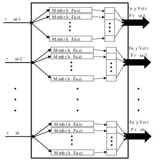
FIGURE 1 - Fuzzification of the crisp numerical inputs.
The Fuzzy Inference Engine
The fuzzy inference engine uses the fuzzy vectors to evaluate the fuzzy rules and produce an output for each rule. Figure 2 shows a block diagram of the fuzzy inference engine. Note that the rule-based system takes the form found in Eq. (1).
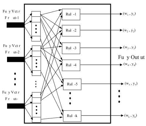
FIGURE 2 - Fuzzy inference engine.
This form could be applied to traditional logic as well as fuzzy logic albeit with some modification. A typical rule R would be:
Ri: IF xi THEN y = Ci (30.7)
where x is the result of some logic expression.
The logical expression used in the case of fuzzy inference (30.7) is of the form
x � Xi (30.8)
where x is the input and Xi is the linguistic variable.
In binary logic, the expression in Eq. (30.8) results in either true or false. However, in fuzzy logic we often require a continuum of truth values. Figures 3 and 4 illustrate the difference between binary logic and fuzzy logic. In traditional logic, there is a single point representing the boundary between true and false. While in fuzzy logic, there is an entire region over which there is a continuous variation between truth and falsehood. The second part of Eq. (30.7), y = Q, is the action prescribed by the particular rule. This portion indicates what value will be assigned to the output. This value could be either a fuzzy linguistic description or a crisp numerical value.
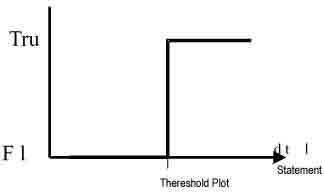
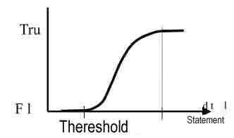
FIGURE 3 - Binary logic statement evaluation. FIGURE 4 - Fuzzy logic statement evaluation.
Defuzzification
The fuzzy inference engine as described previously often has multiple rules, each with possibly a different output. Deffuzzification refers to the method employed to combine these many outputs into a single output. Out of the two methods of defuzzification, the most common method is the fuzzy centroid and is the one employed in this chapter.
Applications of Fuzzy Logic to Electric Drives
High performance drives require that the shaft speed and the rotor position follow pre-selected tracks (trajectories) at all times. To accomplish this, two fuzzy control systems were designed and implemented. The goal of fuzzy control system is to replace an experienced human operator with a fuzzy rule-based system. The fuzzy logic controller provides an algorithm that converts the linguistic control maneuvering, based on expert knowledge, into an automatic control approach. In this section, a Fuzzy Logic Controller (FLC) is proposed and applied to high performance speed and position tracking of a brushless dc (BLDC) motor. The proposed controller provides the high degree of accuracy required by high performance drives without the need for detailed math¬ematical models. A laboratory implementation of the fuzzy logic-tracking controller using the Motorola MC68HC11E9 microprocessor is described in this chapter. Additionally, in this experiment a bang-bang controller is compared to the fuzzy controller.
Fuzzy Logic-Based Microprocessor Controller
The first step in designing a fuzzy controller is to decide which state variables representative of system dynamic performance can be taken as the input signals to the controller. Further, choosing the proper fuzzy variables formulating the fuzzy control rules are also significant factors in the performance of the fuzzy control system. Empirical knowledge and engineering intuition play an important role in choosing fuzzy variables and their corresponding membership functions. The motor drive's state variables and their corresponding errors are usually used as the fuzzy controller's inputs including rotor speed, rotor position and rotor acceleration. After choosing proper linguistic variables as input and output of the fuzzy controller, it is required to decide on the fuzzy variables to be used. These variables transform the numerical values of the input of the fuzzy controller to fuzzy quantities. The number of these fuzzy variables specifies the quality of the control, which can be achieved using the fuzzy controller. As the number of the fuzzy variable increases, the management of the rules is more involved and the tuning of the fuzzy controller is less straightforward. Accordingly, a compromise between the quality of control and computational time is required to choose the number of fuzzy variables. For the BLDC motor drive under study two inputs are usually required. After specifying the fuzzy sets, it is required to determine the membership functions for these sets. Finally, the FLC is implemented by using a set of fuzzy decision rules. After the rules are evaluated, a fuzzy centroid is used to determine the fuzzy control output.
![]()