
At present time synchronous motors are more perspective in view of development of controlled electrical drives. It has a number of preferences in comparison with DC and asynchronous motors. Now there are projects of non-contact synchronous machines with improved energy and overall characteristics.
The purpose of this work: identification of correspondence between mathematical formulation and Powerlib-models and development of guidelines of it’s application.
Synchronous motors are characterized by a variety of constructions. And there are many principles for designing automatic control systems for synchronous motors.
Mathematical formulation of synchronous machines is difficult. There is a system of differential equations. That’s why in process of creation of mathematical models can be made errors. For modeling transient processes in synchronous machines can be used package MATLAB with application Simulink. In this application there is library
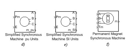
Powerlib where are represented blocks of synchronous machines. This blocks are complete models of synchronous machines (figure 1). But because mismatch in terminology and absence of detail diagrams of this blocks can be occurred some difficulties in determination of block parameters.


Figure 1 – Powerlib-models of synchronous machines
For this next problems must be solved:
• develop own mathematical models in Simulink;
• compare it with Powerlib-models;
• make corresponding resume.
Then the results of this work can be used for analysis and designing automatic control systems for synchronous motors.
Direct acquaintance with attendant documentation, analysis of presented models allowed to make following conclusion.
Blocks "Synchronous Machine" (figure 1a,b,c) models synchronous machines with damper winding (first two blocks in relative units [p. u.], third block in SI units). By the instrumentality of blocks "Simplified Synchronous Machine" (figure 1d,e) we can simulate synchronous machines without damper winding. (p. u. and SI properly). Block "Permanent Magnet Synchronous Machine" (figure 1å) models synchronous machine with permanent magnet.
In figure 2 represented window of parameters of Synchronous Machine SI Fundamental.

Figure 2 – Window of parameters of Synchronous Machine SI Fundamental
The first row specifies rotor type: salient-pole or round (cylindrical); the second – nominal parameters: the total three-phase apparent power Pn (VA), rms line-to-line voltage Vn (V), frequency fn (Hz), and field current ifn (A); the third row specifies stator parameters: the resistance RS (Ohms), leakage inductance Lls (H), and d-axis and q-axis magnetizing inductances Lmd (H) and Lmq (H). The fourth row specifies field winding parameters: the field resistance Rf’ (Ohms) and leakage inductance Llfd' (H), both referred to the stator. The fifth – damper winding parameters: the d-axis resistance Rkd' (Ohms) and leakage inductance Llkd' (H), the q-axis resistance Rkql' (Ohms) and leakage inductance Llkql' (H), and (if round rotor only) the q-axis resistance Rkq2' (Ohms) and leakage inductance Llkq2' (H) (all these values are referred to the stator); the sixth – mechanical parameters: the inertia coefficient J (kg.m2), damping coefficient D (N.m.s./rad), and number of pole pairs p; the last row specifies initial conditions: the initial speed deviation dw(% of nominal speed), electrical angle of the rotor Oe (deg), line currents magnitudes ia, ib, ic (A) and phase angles pha, phb, phc (deg), and the initial field voltage Vf (V).
© DonNTU 2008 Guz