


ÄîíÍÒÓ> Ïîðòàë ìàãèñòðîâ ÄîíÍÒÓ
Transmission Line Fault Detection & Phase Selection using ANN
M. Kezunoic
Keywords – Fault Detection, Phase Selection, Transmission Line Protection, Neural Networks
I. INTRODUCTION
In an electric power system comprising of different complex interacting elements, there always exists a possibility of disturbance and fault. The advent of large generating stations and highly interconnected power systems makes early fault detection and rapid equipment isolation imperative to maintain system stability. Faults on power system transmission lines need to be detected and located rapidly, classified correctly and cleared as fast as possible. Fault detector module of a transmission line protective scheme can be used to start other relaying modules. Fault detectors provide an additional level of security in a relaying application as well.
Application of a pattern recognition technique could be useful in discriminating between power system healthy and/or faulty states. It could also be used to distinguish
which of the phases of a three phase power system is faulty. Artificial Neural Networks (ANNs) are powerful in pattern recognition and classification. Consequently, various ANN-based algorithms have been investigated and implemented in power systems in recent years [1].
A well developed protective scheme should perform well for different system conditions and parameters. ANNs possess excellent features such as generalization capability, noise immunity, robustness and fault tolerance. Therefore, the decision made by an ANN-based relay would not be seriously affected by variations in system parameters.
ANN-based techniques have been used in power system protection and encouraging results are obtained [1-6].
In this paper, a new scheme is proposed for fast and reliable fault detection and phase selection. The proposed method uses an artificial neural network-based scheme.
Various transient system faults are modeled and an ANN based algorithm is used for recognition of these patterns.
Performance of the proposed scheme is evaluated using various fault types and encouraging results are obtained. It is shown that the algorithm is able to perform fast and correctly for different combinations of fault conditions, e.g. fault type, fault resistance, fault inception angle, fault location, pre fault power flow direction and system short circuit level.
II. FAULT TYPE CLASSIFIERS
Conventional fault detection algorithms are designed based on current or voltage magnitude measurements [7,8].
Increase of current magnitude or decrease of voltage/impedance magnitude could be considered as a measure to detect a system fault. These algorithms are dependent on various factors such as fault resistance and power system short circuit capacity. Current based starters get confused when load current is significant compared to fault current. Conventional over current based starters may not be able to detect faults with high amount of fault resistance. For remote low current faults, no clear under voltage condition arises at the relay location. In the case of a close-in fault on a weak system, all voltages deviate from the nominal value.
Therefore, the voltage based starters might not be able to perform correctly for different fault conditions.
For the conventional based fault detectors, current and voltage magnitudes should be estimated correctly using appropriate filtering algorithms. When a fault happens on a
transmission line, the power system goes through a transient period. It might not be easy to determine current/voltage signal magnitude fast and precisely during the transient period after the occurrence of the fault.
As power systems grow both in size and complexity, it becomes necessary to identify different system faults faster and more accurately using more powerful algorithms. It
would be desirable to design a reliable and fast algorithm to classify different power system faults for various system parameters and fault states. An ANN-based algorithm in proposed in this paper as a transmission line fault detector and fault type classifier module.
III. POWER NETWORK SIMULATION
A 230 kV power system is simulated using EMTDC electromagnetic transient program and various types of faults with different system conditions and parameters are modeled [9]. The one-line diagram of the studied system is shown in Fig. 1. Short circuit capacity of the equivalent The venin sources on two sides of the line is considered to be 1.25 GVA. Sources Zo/Z1 ratio and X/R ratio are 0.5 and 10, respectively.
The system transmission line is simulated using Bergron model. The physical structure of the modeled transmission line is shown in Fig. 2.
The training data set of an ANN should contain the necessary information to generalize the problem.
Combinations of different fault conditions were considered and training patterns were generated by simulating different kinds of faults on the power system. Fault type, fault location, fault resistance and fault inception time were changed to obtain training patterns covering a wide range of different power system conditions. The simulated training data set was used to train the ANN-based selector module.
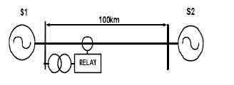
Fig. 1 - Power system model
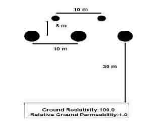
Fig. 2 - Modeled transmission line structure
IV. THE PROPOSED NEURAL NETWORK
A. Network Inputs
Measured currents at the relay location are subject to change when a fault occurs on a transmission line. Fault detection/classification principle may be based upon detecting these changes. The principle of variation of current signals before and after the fault incidence is used and a fast and reliable ANN-based fault detector/classifier module is designed to detect the fault and classify the fault type.
Current waveform signals are sampled at a rate of 20 samples per cycle. Samples of each of the phase currents are compared with the samples of the same phase current taken half cycle and one cycle before. These superimposed signals are made based on the combination of the current samples using equations 1- 3. In these equations SupA,
SupB and SupC correspond to phases A, B and C superimposed signals, respectively. The resultant three superimposed signals are considered as the first three inputs to the designed neural network module.
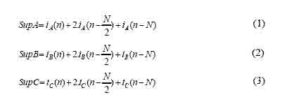
In equations 1-3 n is the sample number and N is the number of samples per cycle.
There is a chance that one cycle after occurrence of a fault, the second cycle fault signals become similar to the first cycle signals and therefore, superimposed signals might decrease considerably. To have stable outputs for a few cycles after occurrence of a fault, one cycle of data from each of the phase currents prior to the fault incidence
is stored in the memory. One cycle after the occurrence of a fault, fault current samples are compared to the prior to fault current samples based on the same principle used in equations 1-3.
Extensive studies were performed and it was found that to be able to design a reliable fault selector scheme which could perform correctly for a wide range of power system
parameters and fault conditions, it is better to add zero and negative sequence components of the three phase currents as the neural network inputs. These two signals are considered as the 4th and 5th inputs of the designed network, respectively.
Using the above input information as the neural network inputs, it was found that the fault detector algorithm is also able to detect fault type changes and behave correctly even for evolving sequential faults.
B. Patterns Generation and Preprocessing
The simulated power system data obtained through EMTDC software simulation are used as the input information to train the proposed neural network. Network training pattern generation process is depicted in Fig. 3.
Preprocessing is a useful method which can significantly reduce the size of the neural networks based classifiers and improve the performance and speed of training process
[10]. Three phase current input signals were processed by simple 2nd-order low-pass Butterworth filters. The filters had a cut-off frequency of 400 Hz which introduces just a small time delay. The low-pass filter frequency response is shown in Fig. 4.
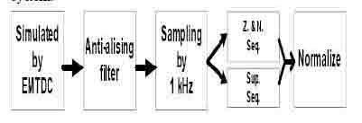
Fig. 3 - Training pattern generation procces
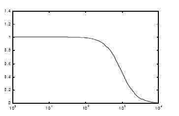
Fig. 4 - Butterworth low-pass filter frequency response
Phase current signals are sampled consecutively and the superimposed inputs of the network are prepared using equations 1-3. To make zero and negative signal inputs of
the network, discrete Fourier transform method is used to obtain currents phasors and then, sequence components are estimated.
Current samples are scaled to have a maximum value of +1 and a minimum value -1. The current signals are divided by the six times of the nominal current of the system.
C. Network Structure and Training
Multilayer feed forward networks were chosen to process the prepared input data. A few different networks were selected initially. For designing the fault selector based
neural network, different networks with 5 inputs and 4 outputs were considered. Four different A, B, C and N outputs were considered to determine whether each of the three phases A, B, C and/or neutral N are present in the fault loop.
The networks' architectures were decided empirically which involved training and testing different number of networks. Three layer networks were found to be appropriate for the fault selector application. For all the networks, hyperbolic tangent function was used as the activation function of the hidden layer neurons. Saturated linear function was used for the output layer [10].
Various networks with different number of neurons in their hidden layer were trained with both conventional Back-Propagation (BP) and Marquardt-Levenberg (ML) algorithms [11]. While BP is a steepest descent algorithm, ML algorithm is an approximation to the Newton 's method. The ML algorithm is a nonlinear least square
algorithm applied to learning of the multilayer perceptrons. It was found that the networks trained with the ML algorithm provide better results compared with the results of the networks trained with the BP algorithm. Therefore, it was decided to use the ML training algorithm for this application.
D. Proposed ANN Structure
Once trained, the networks performance was tested using a validation data set. The suitable network which showed satisfactory results was finally selected. The selected network structure is shown in Fig. 5. The network has 5 normalized inputs and 4 outputs. The number of neurons for the hidden layer is chosen to be 10 neurons.
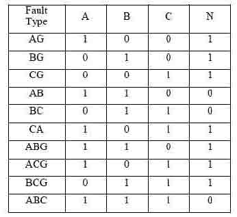
Based on the fault type which occurs on the system, output neurons should be 0 or 1. Outputs which are greater than 0.7 are considered to be active, while outputs less than 0.3 are considered to be inactive. Neural network desired outputs for different types of faults are shown in Table I.
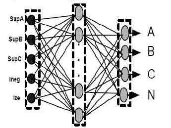
Fig.5 - The proposed network structure
Table 1 - Neural network desired outputs
V. NETWORK EVALUATION
The designed neural network-based fault detector/phase selector module was tested using a validation data set. For different faults of the validation set, fault type, fault location, fault inception time, source impedance and pre fault power flow direction were changed to investigate the effects of these factors on the performance of the proposed algorithm. Extreme cases like faults near to the end of transmission line including fault resistance were also included in the validation data set. For the studies
performed, it was found that the proposed network is able to correctly detect different kinds of faults and to determine the fault type.
The proposed network outputs for a double phase AB fault are shown in Fig. 6. For this case, a fault is applied to the system at the time 57 ms and the network outputs are
shown for about the first 50 ms after the fault inception which is of utmost interest. The fault location was 83 km from the relay location, while the relative angle of the sending-end source with respect to the angle of the receiving-end source was 10 degrees. As shown in this figure, the network is able to respond to the fault correctly
in a timely fashion. The fault is identified just in a few ms which shows that the network is able to detect and classify the fault quite fast. The network outputs remain stable after identifying the fault.
Network outputs for an evolving short circuit fault at 80 km are presented in Fig. 7. For this sequential fault, first a single phase to ground AG fault is applied and the fault is identified correctly. Then, at the time 68 ms the fault is changed to a double phase to ground ABG fault. As shown in Fig. 7, the network responds to this change accordingly.
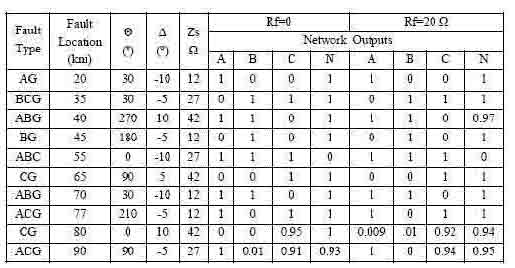
The proposed network performance for a few faults with different power system conditions is presented in Table II.
As an example, test results for a single phase to ground AG fault at 20 km from the relay location is presented in the first row of Table II. For this fault, the relative angle of the sending–end source with respect to the angle of the receiving-end source, ? was -10 deg. The fault inception angle ? with respect to phase A voltage zero crossing was 30 deg and the source impedance Zs was considered to be 12 ?.
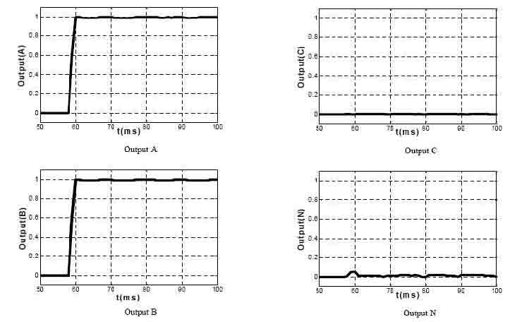
Fig. 6 - Network outputs for a fault at 83 km

Fig. 7 - Network outputs for an evolving faults
Network outputs for two different amounts of fault resistance are shown in the last columns of the table. For the above AG fault, the A and N outputs of the network are
activated while the B and C outputs remain zero.
For the faults which do not involve ground, fault resistance is not a critical factor. For these types of faults usually fault detectors could detect the fault more easily.
Therefore, in Table II the main emphasis is for the faults which involve ground as well.
As shown in Table II, the relay performs quite reliably for a wide variety of fault types and system conditions. For the faults including high amount of fault resistance,
conventional fault detectors response is slow in nature and even they might not be able to detect the fault due to low level of fault current. However, designed network could perform well even in the presence of considerable amount of fault resistance.
As an example, the network response for a CG fault at the end of the transmission line with 20 ? fault resistance is shown at one row before the last row of Table II. For this case, the source impedance is high as well, so the system fault level is quite low. The fault is identified correctly as shown in Table II even for this fault which has low level of fault current.
Table II - Proposed algorithm test results
Performance of the proposed scheme is evaluated using various fault types and encouraging results are obtained. It was shown that the algorithm was able to perform fast and correctly for different combinations of fault conditions, e.g. fault type, fault resistance, fault inception angle, fault location, pre fault power flow direction and system short circuit level.
VI. CONCLUSIONS
In this paper a new approach to fault detection/phase selection algorithm is presented and its effectiveness is demonstrated. The suggested approach is based on the use of neuron computing technology and implementation of pattern recognition concepts. The paper presents a positive approach to improve the performance of conventional algorithms.
The proposed algorithm is extensively tested by independent test fault patterns and promising results are obtained. Effects of different system parameters and conditions is studied. Extensive studies indicate that the network is able to classify different faults correctly and rapidly and its performance is not affected by the changing network conditions.
REFERENCES
[1] M. Kezunoic, “A Survey of Neural Net Application to Protective Relaying and Fault Analysis”, Eng. Int. Sys., Vol. 5, No. 4, Dec. 1997, pp. 185-192.
[2] M. Sanaye-Pasand and O.P. Malik, “High Speed Transmission System Protection Using an Elman Network”, IEEE Trans. On Power Delivery, Vol. 13, No. 4, Oct. 1998, pp. 1040-104
© DSTU 2008 Maslov