INDUCTION MOTOR PARAMETER IDENTIFICATION FROM OPERATING
DATA FOR ELECTRIC DRIVE APPLICATIONS A.B. Proca, Department of Electrical Engineering, The Ohio State University, Columbus, OH 43210
INDUCTION MOTOR PARAMETER IDENTIFICATION FROM OPERATING DATA FOR ELECTRIC DRIVE APPLICATIONS
A.B. Proca, Department of Electrical Engineering, The Ohio State University, Columbus, OH 43210
A. Keyhani, Department of Electrical Engineering, The Ohio State University, Columbus, OH 43210
Introduction
Parameter identification is critical for high performance control strategies in which both dynamic performance and energy efficiency are expected.
This paper describes the methodology of identifying the parameters of an induction motor in electric drive applications. The authors use operating data to estimate the parameters, therefore obtaining a more realistic representation of the parameters. As most of the parameters vary with the operating conditions, the authors show that a mapping exists between the operating conditions and the motor parameters.
Problem statement
In classical induction motor control, speed is sought as the variable to be tracked. Also, in most speed control applications efficiency is not an important goal in control due to the relatively high efficiency of induction motors. As a consequence, the flux level of the motor is kept at constant level (usually rated value) and only decreased if high-speed operation is needed.
In automotive applications, in which the motor acts as a stand-alone propulsion system or in combination with an internal combustion engine (as in the case oh hybrid electric vehicles) torque is usually the control variable. Furthermore, efficiency is important due to the limited capacity of the batteries that supply the motor and their long (and inefficient) recharging cycles.
In high performance applications, the induction motor is controlled through field orientation techniques. Since these techniques require the knowledge of the motor model parameters, a mismatch in parameters is prone to create control errors.
However, for speed control applications in which the speed is measured, the errors introduced by the parameter mismatch can be compensated using a series of properly designed PI controllers.
In torque control applications, torque is impractical to be measured and therefore is estimated using measurements of currents and estimations of fluxes (generated by flux observers). A mismatch in parameters will generate erroneous flux estimation and consequently erroneous torque estimates. The motor will track a wrong torque reference.
Automotive applications also require maximum efficiency operation for the motor. This goal that is commonly achieved by appropriately adapting the motor flux levels to the load. A parameter mismatch will introduce errors not only in the flux estimates but also in the optimal flux calculation. As a consequence, the motor will not only produce an erroneous torque but will also operate at non-optimal efficiency.
The induction motor parameters vary with the operating conditions, as is the case with all electric motors. The inductances tend to saturate at high flux levels and the resistances tend to increase as an effect of heating. There are other effects that contribute to the parameter variation, which make the dependency between operating conditions and parameters even more complicated. Most of previous research in motor control uses a single set of parameters for all operating condition or uses on-line adaptive procedures for the estimation of only one parameter, namely the rotor resistance. As shown earlier, using a single set of parameters for all operating conditions is prone to introduce errors if torque control at maximal efficiency is sought.
This paper presents a procedure of estimating the motor parameters at all operating conditions and mapping them to these conditions.
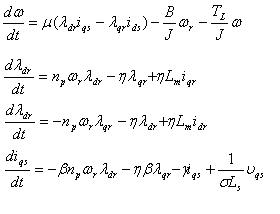
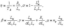
Induction motor model
The stationary reference frame model of the induction motor is used in this research. The model is shown in Fig.l
The equations that describe the model
are:
with constants defined as follows :
where Rs— stator resistance
Rr- rotor resistance
Lm — magnetizing inductance
L1s - stator leakage inductance
L1r - rotor leakage inductance
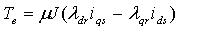
The electromagnetic torque is:
References
1. G.S.Kim, I.J. Ha, M.S. Ko, "Control of
induction motors for both high dynamic
performance and high power efficiency ",
IEEE Transactions on Industrial Electronics
v39n4 1992p.323-333
2. O. Wasynczuk, S.D. Sudhoff, I.G. Hansen,
L.M. Taylor, K.A. Corzine, J.L. Tichenor,
P.C. Krause, " Maximum torque per ampere
control strategy for induction motor
drives", IEEE Transactions on Energy
Conversion v 13 n 2 1998 p.163-169
3. T.A. Lipo, A. Consoli, "Modeling and
simulation of induction motors with
saturable leakage reactances", IEEE
Transactions on Industry Applications v IA-
20 nl 1984p.l80-189
4. J.A. de Kock, F.S. van der Merwe, H.J.
Vermeulen "Induction motor parameter
estimation through an output error
technique", IEEE Transactions on
Energy Conversion v 9 n 1 1994 p.69-76
5. S. I. Moon and A. Keyhani, "Estimation of
Induction Machine Parameters from
Standstill Time Domain Data,", IEEE
Trans, on Industrial Applications, Vol. 30,
No. 6,Nov/Dec 1994
6. W. Leonard, Control of Electrical Drives,
Springer, Berlin, Heidelberg, 1985
7. B. K. Bose, Power Electronics and AC
Drives, Prentice Hall, 1986.
8. M. Bodson, J. N. Chiasson, R. T. Novotnak,
"A Systematic Approach to Selecting Flux
References for Torque Maximization in
Induction Motors", IEEE Trans, on Control
System Tech. Vol. 3, No. 4, pp 388-397,
1995