


By James Cobbs, PE, and David Cobbs, PE, Cobbs Engineering, Tulsa, Oklahoma
Through the years, a number of drilled shaft lining systems have evolved with each of the systems having special applications. Each step, from design through installation of a lining system, is critical.
The causes of lining failures range from inadequate design to inadequate quality control during fabrication, to errors during installation and grouting.
Probably the oldest lining technique for drilled shafts has been grouted-in-place steel linings. Steel linings offer the lowest K factor for ventilation shafts, and this can be a real advantage. Several variations of the steel lining are possible.
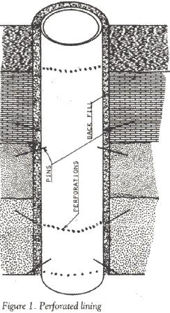
Where water inflow is not a problem, a simple perforated steel liner can be installed (Figure 1). The lining is usually of relatively thin wall so the pressure capacity of the lining is low. To prevent the accumulation of water behind the liner, it is perforated so that any water can drain into the shaft. The strength of the lining is greater if it is loaded symmetrically. The lining is pinned to the shaft walls with bolts and the annulus is backfilled with sand or gravel.
The earliest linings where fluid inflow prevention was a factor, the diameters small, and depths not great were grouted-in-place smooth wall steel liners. The pressure capacity of smooth liners is analogous to a slender column where the controlling factor is the modulus of elasticity rather than the strength of the steel. Because of this, the pressure capacity decreases rapidly as the diameter increases. Pressure capacity is also adversely affected by any out-of-roundness in the liner. There have been a number of liner failures, usually when grouting, when the pressure imposed on the outside of the liner exceeded its pressure capacity. It has been well documented by the American Petroleum Institute and others investigating the possible reinforcement of steel by grout, that regardless of the efforts exerted in the placement of grout, the steel lining will experience the full hydrostatic pressure of any contained fluids. Thus the steel tube must be designed to resist the full hydrostatic pressure expected with a suitable safety factor. Since the pres-sure expected will increase with depth, it is common to inctease the wall thickness of the lining as the depth increases.
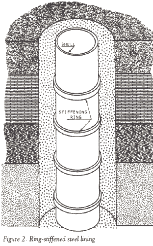
To counter the slender column effect of a smooth steel lining, ring-stiffened steel linings were developed (Figure 2). As depth and diameters increased, along with the pressure to be resisted, the weight and cost of the smooth linings increased dramatically. A well-designed ring-stiffened steel liner of about 48 inches or greater diameter is less expensive than a smooth steel liner of comparable diameter and pressure capacity. The design procedure for a ring-stiffened steel liner is almost identical to the procedure for the design of the pressure hull of a submarine. The pressure capacity of a stiffened lining is determined by the strength of the steel, the wall thickness of the shell, the spacing of the stiffening rings and the moments of inertia of the rings.
There are three modes of failure for a ring-stiffened liner: general instability collapse of the combined shell and rings, elastic collapse of the shell between rings, and a yielding failure of the shell between rings.
The first two failure modes are related to the wall thickness, stiffener spacing, stiffener moment of inertia of the rings and the modulus of elasticity of the material. The design technique then is to develop a combination of stiffeners and shell which will take advantage of the strength of the steel. Because there are an almost infinite combination of variables possible in the design process, optimization of the design co achieve minimum weight and cost requires the analysis of a very large number of geometries. This then lends itself to a computer analysis procedure. We have developed and used (me of the few, if not the, only, computer optimization procedures for the design of ring-stiffened steel linings.
Kerr-McGee developed a combination lining system in the Grants area of New Mexico which used a high-pressure lining opposite the principal aquifers with perforated steel opposite the dry zones. This technique was especially valuable in this area because there are three principal water-bearing zones and the balance of the formations are dry. If there was any water accumulation behind the weaker lining sections, it could drain through the perforations in the thin shell. This technique can be applied where there are well defined aquifers and the majority of the formations drilled are dry.
Because the cost of a steel lining increases rapidly as the diameter and pressure requirements increase, alternative linings have been sought. A system which was developed in Germany and used in Canada combined a thin steel outer shell for pressure containment with a relatively thick concrete lining. The steel and concrete are tied together with steel studs welded to the inside of the steel shell. A further refinement of this system is the use of a thin steel liner on the inside of the concrete, as well as the outer shell. Because of the higher modulus of elasticity of steel, compared to concrete, the use of two steel shells is usually economically justified. The design procedure for this type of lining is essentially the same as for a smooth steel lining, with the contribution of the concrete decreased by the ratio of the moduli of elasticity of the steel and concrete.
The modulus of elasticity of concrete is only about one-fifth that of steel so the thickness of a composite lining will be much greater than a ring-stiffened steel lining of the same internal diameter. This increased lining thickness will require a larger diameter hole for a given internal diameter.
The steel shell or shells are welded as the liner is run in the hole for pressure integrity. Because the concrete can be adversely affected by the heat of welding, a gap in the concrete is maintained. Provision is made for the grouting of this gap after the weld or welds have cooled and before the joint is lowered in the hole.
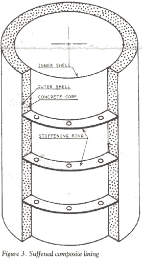
To take advantage of the effect of stiffening rings, a composite lining can have steel rings between the two steel shells as reinforcement (Figure 3). This can reduce the wall thickness requirements of the lining and, in turn, reduce the diameter of the hole required to accommodate the lining of a specified internal diameter. This, of course, will be a more expensive composite lining but may result in the most economical shaft when the drilling cost of a larger diameter is considered.


