field of the inventionThe present invention relates to continuous casting machines, and more particularly to the automatic control of secondary cooling in continuous casting machines. background artContinuous casting machines are used in the basic metal industry to continuously produce semifinished billets, slabs, and the like from molten metal in a one-step solidification process. Generally, molten metal from a tundish is continuously introduced into a water-cooled mold where initial solidification takes place in the form of a frozen metal skin surrounding a liquid core as the cast product continuously leaves the mold. The molten metal continues to solidify progressively inwardly in a secondary cooling zone where complete solidification of the cast product occurs in the spray cooling, roll cooling and radiation cooling zones located beyond the caster mold. In order to have successful caster operation, a precise amount of solidification or skin growth must continuously occur. If too much heat is removed, surface cracks and internal defects may develop in the strand. If too little heat is removed, a breakout of molten metal will occur in the caster which may result in serious consequences to both personnel and facilities. Therefore, it is important to continuously control the caster heat removal rate for preventing problems which can occur in the continuous casting operation. Early casters had only simple control of spray cooling water rates. The flow in each zone was usually set before each cast and remained constant. As more grades with greater temperature sensitivity were cast a better means of cooling control was needed. A first known method for controlling the cooling of the cast product in a continuous casting involves controlling the flow in each zone as a direct function of casting speed. In this method, the cooling water rates are correct only when steel passing through a spray zone has traveled at a steady speed from the time it started at the meniscus. When speed changes occur, the strand will experience temperature perturbations until fresh steel at a new steady state fills the spray chamber. These temperature disturbances can cause surface and internal defects. To overcome this deficiency, a second known method has been the control of flow as a function of the steel residence time in each zone. With residence time control, theoretically each element of steel entering the machine is cooled in the same way since time is the controlling factor. As speed changes, the entire cooling profile along the machine changes. For example, if the maximum speed is reduced by 50% then the new steel entering the machine is cooled in 50% of the spray distance. This known method of controlling the coolant water flow as a function of the steel residence or elapse time in each zone is described, for example, in British Patent Specification No. 1,302,040 published on Jan. 4, 1973 and in U.S. Pat. No. 4,463,795 to Chielens, et al. In the Chielens, et al. patent, there is described a predictive method of controlling cooling by making residence time calculations and water flow calculations using heat transfer curves. Although the residence time technique is an improvement over previous control methods, important deficiencies still exist. The residence time is a purely predictive control based on calculations, while correct cooling requires that flows follow the computing setpoints. This is not possible in many instances due to mechanical and operational caused problems including the process hardware limitations described below. summary of the inventionIn view of the above, it is an object of the present invention to improve the secondary cooling oepration in continuous casting of metals by providing a flow control action which supplements the residence time computed flow. It is another object of the present invention to provide a supplemental control action in the continuous casting of metals which eliminates or minimizes the possibility of overcooling and undercooling by such corrective action for situations that the feedforward residence time technique cannot anticipate. It is another object of the present invention to improve the secondary cooling control in continuous casting to correct for both transient effects due to start-up of a cold machine and variations in the actual effective secondary cooling occurring along the strand. It is another object of the present invention to increase the effective nozzle range to below the practical minimum flows. It is a further object of the present invention to provide a method for utilizing an existing secondary cooling practice from a nonresidence time, speed-flow control technique in conjunction with a residence time calculation technique. It is a further object of the present invention to correct for the disadvantages of employing a predictive coolant control in a continuous casting by incorporating both calculated and measured coolant criteria on a continuous basis for correcting the coolant control. These and other objects are achieved by the present invention which provides a method of cooling a continuous casting, comprising determining for each element of steel the steel residence time in each cooling spray zone of the secondary cooling zone and using the residence time for each zone to determine the required cooling for that zone, controlling the coolant water flow as a function of such steel residence time in each zone, giving a residence time computed quantity of cooling water that an element of steel should receive in each zone, if it were traveling at such average casting speed, determining residence time zone flow rates as a function of average speed, grade, mold heat removal and section size of the strand, measuring the total quantity of specific flow (gal/ft 2 ) that each element of steel has actually received from the sprays and computing such amount, calculating the specific flow (gal/ft 2 ) in a zone that would be for the average speed, grade, section size, and mold heat removal, and comparing the computed reference specific flow in each zone and the measured specific flow of cooling water (gal/ft 2 ) actually received in that zone to provide a coolant flow correction used as a feedback signal for modifying the residence time zone flow rates. Such modified residence time flow rate is used as the control flow in conjunction with the measured specific flow, computed reference specific flow, and the computed maximum specific flow, to determine if the flow is to be used, or to shut off the flow or to cycle it on and off. The use of the measured value of actual coolant flow to the elements in each zone thereby provides a feedback control for the coolant water control action and thereby supplements the residence time computed flow. The secondary cooling spray chamber is divided into a number of zones which contain a set of spray water nozzles. Cooling is carried out on a zone-by-zone basis. For all elements of the strand, a specific flow is maintained from the first element exiting the meniscus to the last element leaving the cooling chamber. The specific flow is the integrated water than an element has accumulated from the time the element first entered the spray chamber to the present time. All the elements of specific water flow taken together are known also as the water history which represents the accumulated water on strand elements from the beginning of the spray chamber to the end of the spray chamber. The specific water history shows the actual gallons per square foot of water applied to the differential elements of the strand and is used in calculating the required amount of gallonage cooling for each zone. This specific water for the element is averaged, and, in addition, a setpoint is produced for that zone. The feedback flow control loop employs the actual measured specific flow in gallons per square foot and compares it with the reference specific flow to determine the error flow signal used for correcting or modifying the residence time flow rates as described above. The actual measured specific flow is also used to determine whether the system is to use such modified residence time flow or to shut off the flow. This is done by calculating, from the reference specific flow, the maximum specific flow that the system will not be permitted to exceed. This maximum reference specific flow is compared with the measured specific flow and, if the measured specific flow exceeds the maximum reference specific flow, the system flow will be shut off. This is the MAXFLO subroutine which uses the actual measured specific flow feedback for correcting the coolant flow and maintaining the setpoint. In this fashion, the present invention improves the present residence time approach to continuous casting secondary cooling methods by adding a feedback route which monitors the actual amount of coolant provided to the strand in each spray zone. The measured value of cooling water for each zone is used to determine the additional flow control action to supplement the residence time computed flow. This supplemental control action may trim the residence time flows to remove small disturbances for such action or shut off a zone entirely when the strand has received the total quantity of cooling required. The additional feedback in this manner eliminates the possibility of overcooling and applies corrective action for situations that the feedforward residence time cannot anticipate; such as when a cooling failure occurs in one zone, the following zones will apply a corrective action. Furthermore, the system enhances the control of secondary cooling by modifying the cooling practice to take into account additional process characteristics not previously accounted for. Control of secondary cooling is also enhanced by the present invention by increasing the effective nozzle range to below the practical minimum flows by cycling the minimum flow on-off. Finally, the subject invention provides a method for utilizing the existing critical secondary cooling practice from a nonresidence time control scheme in conjunction with a residence time calculation technique. DESCRIPTION OF THE PREFERRED EMBODIMENTSReferring to FIG. 1 there is shown a continuous metal caster 10, or simply a caster 10, which is shown after start-up, operating in essentially a steady-state mode. Super-heated molten metal was teemed form a ladle 11 into a tundish 12 and then fed controllably by shroud 13 into a caster mold 14. Mold 14 is cooled by flow regulated by flow control valve (WCV) 17, and effects solidification so that as cast strand 15 leaves mold 14 it continually consists of a liquid core and outer shell or skin of sufficient thickness to prevent a breakout. Mold 14 instantaneous heat removal requirements vary as a function of mold hot metal level, mold size, other parameters described below, and cast strand 15 withdrawal rate as determined by pinch roll 16 operating in a preset speed control loop. In the case of mold 14 being an adjustable rectangular structure with four independent coolant flow circuits, each circuit has a flow control valve WCV interposed between coolant supply 18 and coolant return 19. The mold, ladle and tundish controls are indicated by numeral 21. Computer 20 instrumentation is exemplified by an assembly of conventional computer and control elements such as are described in detail below and also includes the spray zone cooling control system 28 of the present invention. Referring again to FIG. 1, the continuous casting system includes the curved mold 14 which provides a uniform shell growth, the molten steel contained in a solidified shell passing and cooled by water sprays and passing between a plurality of intermediate support rolls 23 which are internally and externally cooled and curved from the vertical toward the horizontal, such rolls 23 being supported by a structure in a conventional manner for producing a curved ingot or strand 15 to be formed and diverted into a horizontal path as defined by the rollers 23 in a radiation and roll cooling section 24. The cast strand 15 passes through a series of withdrawal pinch rolls 16 disposed along a horizontal plane for straightening the strand 15 and motor driven for withdrawing the strand 15 at the selected rate. After leaving the mold 14, the internally molten ingot or strand 15 passes into a spray cooling region defined by a spray chamber 25 within which a plurality of high velocity spray heads 26 are mounted along the path of the strand 16 with rate control valves 27 controlling the coolant, commonly water, to be sprayed onto the strand as it passes along the path in the spray chamber. Spray chamber 25 is divided into a number of zones indicated in greater detail in FIG. 2, each zone containing a set of such spray water nozzles 26 shown in FIG. 3. Cooling is carried out on a zone-by-zone basis. As shown in FIG. 2, zones Z1 to Z11 are shown and it is noted that such zones are further broken down into slices, or differential elements in the calculation of cooling for purposes of providing the most appropriate setpoint, grade and cooling data for carrying out the method of the present invention. As the steel passes through each zone, the measured specific flow, the reference specific flow and the residence time flow rate are used to determine a corrected or modified residence time flow rate. The flow rates of each of the coolant spray zones are determined by the secondary cooling control system with measured flow rate feedback loop described in detail below in accordance with the present invention. The spray water is withdrawn from the areas of the strand 16 at the downstream end of the nozzles 26 through a conventional conduit system having temperature sensors, not shown, for determining the amount of heat withdrawn in the spray cooling chamber. Referring again to FIG. 1, a zone cooling control system 28 is provided for computing a setpoint on line 29 which provides a flow control signal to a flow-indicator-controller 30 for controlling the individual water zone valves 27 via line 31, and the measured flow from the meter 33, in each zone such that the setpoint flow is maintained. The feedforward action of the zone cooling control system is deriving the setpoint based on the conventional residence time approach and is improved by the present invention involving a feedforward-feedback system, wherein there is added to the residence time, feedforward system a feedback, shown in dotted line 32, which monitors via a plurality of flow rate measurment devices 33, the actual flow passing through each set of nozzles 26 in the zones, and feeds back such measured rate signal on feedback line 32 to the zone cooling control system 28. As will be described in more detail below, this measured value of actual cooling supplied to the strand 15 in each zone is also used in the zone cooling control system 28 to determine the additional flow control action for supplementing the residence time computer flow. FIG. 4 is a general functional block diagram of the zone cooling control system shown in FIG. 1. The residence time approach is indicated in the feedforward loop wherein the residence rim 40 for strand 15 in each cooling zone is computed and used to compute the average speed in each zone, as indicated at 41. Setpoints for the secondary cooling zone flows are computed with a digital control algorithm. The primary characteristics of the algorithm are described below. Detailed logic flow diagrams for the computer code are described below. Each major function is executed through a Fortran subroutine. The residence time in a zone is determined at 40 using a subroutine RESTIM. Here, the residence time of the strand in each spray zone is determined using an array containing values of total cast length, time into the cast, and average casting speed, for all elements comprising the entire strand length generated during small time increments. The average casting speed is determined 41 by the subroutine RESTIM with the equation below. 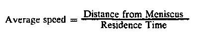 In a pure residence time model, there is one curve for flow or relative cooling versus residence time. The residence time for a zone is used in conjunction with the single curve to find the required cooling for that zone. In an existing caster, where the steady state cooling practice has been developed over a long period of time, to minimize defect formation, it is desirable to maintain this practice with the residence time control scheme. Each zone has individual flow versus speed curves indicated at 42 in FIG. 4. For digital control, the zone residence time at 40 is converted to an average speed at 41 which is used in conjunction with the speed versus flow curves at 42 to define the zone flow on line 43. Thus, at steady state the existing cooling practice is maintained, whereas during transients, the residence time control technique maintains proper cooling. A MAIN control in computer 20 calls the subroutines. The calculated value of cooling, in gallons per minute is provided on line 43 to a summing device 44 which also receives on line 45 a flow correction setpoint signal based on the actual measured and computed specific flows at 48 and 49. The measured specific flow (Subroutines GCALC, FLUX and AVEG) is the total accumulated quantity of specific cooling water each element of steel has received from the sprays and is computed at 46. Average values are found for each zone from all of the elements residing in the zone. A reference aim of the specific flow (Subroutine AIMG), or the total effective quantity of specific flow, an element of steel should receive when it reaches the center of each zone is computed at 47. These values are setpoints for the feedback loops. This calculation of the reference flow at 47 includes a flow rate subroutine SWABH wherein zone flows are computed as a function of average speed, grade and section size of the elements in the zone. Correction factors are applied for start-up and mold powder effects. The reference flow calculated at 47 also includes a strand width subroutine WIDTH which determines the strand width for each zone to be used in computing flow and allows for radical or gradual width changes. The reference flow calculated at 47 also includes a subroutine GRADE which determines which grade will be used for computing the flow in a zone containing 2 different grades. The subroutine determines the position and efective length of the controlling grade for computing flows. Also the reference specific flow calculated at 47 includes a mold powder effect subroutine MOLDQ which determines a flow factor for each zone to take into account the thermal effectiveness of mold powder on secondary cooling. The thermal effect on spray cooling is estimated from the actual heat transfer rate effected in the mold by the powder. The feedback flow control loop employs the actual measured specific flow on line 48 and compares it in amplifier 50, with the reference specific flow on line 49 to determine the error flow rate signal on line 45 used for correcting or modifying the residence time flow rates on line 43 by means of summing device 44. This produces a modified residence time flow signal on line 51A in output flow device 52. The actual measured specific flow on line 48 is also used to determine whether the system is to use such modified residence time flow or to shut off the flow. This is done by calculating at 53, from the reference specific flow, on line 49, the maximum specific flow that the system will not be permitted to exceed. This maximum reference specific flow is compared with the measured specific flow on line 48 in a decision box Maxflo Comparator 55 and, if the measured specific flow exceeds the maximum reference specific flow, the system flow will be shut off via line 51C. This is in the MAXFLO subroutine which uses the actual measured specific flow feedback for correcting the coolant flow rate and maintaining the setpoint by means of the Maxflo Comparator 55 which provides either a modified residence time flow signal on line 51A, a cycle-flow signal on line 51B or a zero flow signal in line 51C for the output flow device 52. Thus, from the system shown in FIG. 4, the zone control strategy of the present invention improves the present residence time approach to continuous casting secondary cooling methods by adding a feedback route which monitors the actual measured amount of coolant provided to the strand in each spray zone. The measured specific flow is then used to determine the additional flow control action to supplement the residence time computed flow. FIG. 5 is a functional block diagram of the system for providing the spray cooling zone control strategy shown and described with respect to FIG. 4 including the feedback technique of the present invention. Flow rate calculator 54 computes the amount of cooling water required for each zone. The flow rate calculator 54 uses the residence time and speed provided respectively by residence time calculator 56 and speed calculator 58 and produces a residence time flow rate signal on line 62 to the setpoint summing device 44, as described as shown in FIG. 4. A specific flow generator 60 calculates a program subroutine AIMG which is defined as the effective quantity of specific water flow that a strand element should receive when it reaches the center of each zone. The values calculated in the subroutine AIMG become the setpoints for the feedback, cycling and shut off loops and are shown in FIG. 5 as being applied by the zone flow generator 60 via line 61 to a reference specific flow calculator 63 which calculates the reference specific flow for the feedback signal. A comparator 66 compares the reference specific flow from calculator 63 with the output of specific flow measurement devices 68 which provides a calculation of the total measured quantity of specific cooling water that each zone has received from the amount of specific water each element in the zone has received. More particularly, a water history generator receives data on each strand element and maintains a water history in terms of gallons per square foot applied in a zone. This record is maintained for every strand element. This difference is provided as the feedback error signal out of comparator 66 on feedback line 64 to the setpoint summing device 44. In this fashion, the system applies the error between the measured specific flow and the reference specific flow to derive the feedback error for modifying the feedforward flow rate. This feedback control operation is described above as the subroutine FEEDBK wherein the aim specific flow is used as a reference or setpoint and the measured specific flow is used as a feedback signal with the feedback control applying a flow correction for maintaining the flow setpoint. The modified residence time flow signal on line 51A is operated on by decision box 55 in output flow device 52 to determine whether the flow should be further modified by cycling or whether the flow setpoint should be set to zero. The output from flow output device 52 is applied on line 29 to the flow input control 70, also indicated as the flow input control 30 to FIG. 1, for converting the setpoint signal to an individual signal for controlling the water control valves associated with each spray zone. FIGS. 4 and 5 show the method and system described above for providing the flow input control. The secondary cooling control method provided by the system shown in FIGS. 1, 4 and 5 will now be described with respect to the flow control diagrams shown in FIGS. 10-14. Initially, the method of generating the flow setpoint will be described with respect to a mathematical model which functions in the following manner. Generally, the cooling chamber is divided into a number of zones, each containing a set of spray water nozzles, and the cooling is done on a zone-by-zone basis. The zones are further broken down into slices, or differential elements, for computation purposes. As the steel passes through a zone, a specific flow (gal/ft 2 ) is generated for each element in the zone. These specific flows are averaged, and a setpoint is produced for that zone. The dynamic modeling and control procedure has a twofold function. Namely, it must run the dynamic modeling program, and provide all interaction with, and control over the cooling process in the real world. Once heat data has been received, the dynamic molding program can be run in independent modes for each strand. It should be pointed out that certain quantities have default values enabling the model to run in the absence of data-link or manually input data. In the example used to further explain the control method certain quantities are used as follows:
Under the dynamic modeling procedure, the system treats each strand as if it were broken into sections or differential elements. The length of each element is configurable, with a minimum length of one inch. For each element of the strand, a specific water flow is then maintained from the time the element exits the meniscus until it leaves the cooling chamber. The cooling chamber is divided into eleven sections, known as zones, and the cooling water is applied by zone. This facilitates a more precise control of the rate of cooling for each differential element. The dynamic model produces setpoint updates for the cooling water zones on a once per two second basis. As each element exits the mold, a time stamp is attached to it, and the mold heat removal ratio is calculated for that element as follows: 
Under normal conditions, superheat is calculated from: Superheat=Tundish temperature — Liquidus temperature In the event that the analog signal for tundish temperature is determined to be invalid, the default value of 40 degrees F. will be used for the superheat. In deriving the cooling requirement for a given zone face, the model proceeds in the following manner: (1) The flow is read from an analog flow measuring device for each zone. This is shown as step 110 in FIG. 10. (2) The current setpoint is applied to a flow control emulator. This produces an expected flow which is then compared to the measured analog flow for the given zone. If the deviation between the measured flow and expected flow exceeds preconfigured limits, the results are provided as an on/off signal or as an alarm to a computer room printer, not shown. This is shown in steps 112, 114 and 116. (3) The current flow is then checked to be in real limits. If the flow rate for a zone is found to be out of real limits, the results are alarmed to an event logger and to a workstation. The system will then assume the flow signal is incorrect and will use the expected flow for all further calculations until such time as the flow rate comes back in limits. At this time, the measured flow rate will be used again. If the flow rate is found at 118 to be within limits, the system will use the measured flow rate for calculations in this iteration of the math model. The amount of water falling on a square foot for a time step in each zone (GAL/FT2) is then calculated using the flow rate decided upon in steps 2 and 3 above, as shown in FIG. 11 at 120. 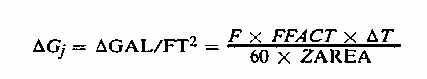 Where: F=The flow rate decided upon in the above steps 2 and 3 measured in gallons per minute FFACT=Flow effectiveness factor for a given zone face to take into account the efficiency of the spray nozzles in each zone. ZAREA=Area of a given zone face, ft2 AT=Time step between computations, =2 seconds j=Zone index It is noted that the elements crossing a given zone have their incremental specific flow multiplied by a weighting factor to correctly model the amount of water they receive from the two zones they straddle. These are updated at 124: 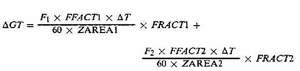 Where: AGT=Incremental specific flow for a transition ele¬ment, GAL/ft2 Fl=The flow rate in the first zone. F2=The flow rate in the second zone. FRACTl=The fractional portion of the transition element which is in the first zone FRACT2=The fractional portion of the transition element which is in the second zone ?T=Time step between computations, 2 seconds ZAREA1=Area of the element in the first zone, ft 2 ZAREA2=Area of the element in the second zone, ft 2 the mold heat removal ratio for this zone thus: 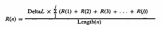 Where: R(n)=The mold heat removal correction factor for the nth zone DeltaL=The length of a differential element R(j)=The mold heat removal ratios for the jth element in the ith zone Length(n)=The length of the nth zone The zone mold heat removal ratio is used to determine a mold powder correction factor. Using the average residence time, compute the J0 average speed and pick a feedforward flow rate off of the current SPC curve for this zone. The SPC curve is defined by the Spray Practice Curve for a particular grade of steel. Adjust this using the average width of the zone, and the width adjustment curve for this 55 strand, zone and grade. This is shown at 132 in FIG. 12 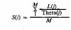 Where: S(i)=The average speed for zone i M=The number of elements of the summation Theta(j)=Residence time of the jth element L(j)=Distance of the jth element from the meniscus. The transition elements for a zone are not included in this average speed. The elements used for calculating Si above are: ZONES 1, 2 and 3: every element ZONES 4 thru 7: every 2nd element ZONES 8 thru 11: every 3rd element Regarding element lengths: ZONES 1, 2 and 3: Elements are 1 inch long ZONES 4 thru 7: Elements are 2 inches long ZONES 8 thru 11: Elements are 4 inches long Calculate the GAIM for this zone as shown by step 141 in FIG. 13 thus: 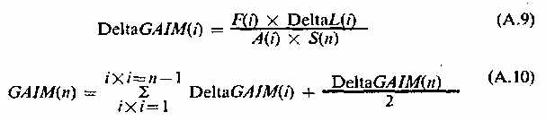 Where: DeltaGAIM(i)=The change of cooling for the ith zone F(i)=Effective flow rate for the ith zone DeltaL(i)=Zone length for the ith zone A(i)=Effective area of a given face for the ith zone. S(n)=The average speed of the elements in the nth zone from equation. DeltaGAIM(n)=The change of cooling for the cur¬rent zone under consideration GAIM=Accumulated cooling for the current zone under consideration n=current zone under consideration While the invention has been described above with respect to its preferred embodiments, it should be understood that other forms and embodiments may be made without departing from the spirit and scope of the invention. What is claimed is: 1. Method for cooling a continuous casting in a cool- ing area that is divided into a plurality of zones in which cooling water spray nozzles are located, comprising: determining a residence time computed cooling water flow rate that an element of steel should receive in each cooling spray zone if traveling at an average casting speed computed from the residence time in said zone; measuring the total specific flow of cooling water that each element of steel has actually received in each spray zone; calculating a reference specific flow in a spray zone related to the average speed, grade, section size and mold heat removal; comparing the computed reference specific flow in each zone with the measured specific flow of cool¬ing water actually received in each said zone to produce a coolant flow rate correction feedback signal; and modifying said computed residence time zone flow rates by said coolant flow correction feedback signal. 2. Method as recited in claim 1 further comprising calculating a maximum specific flow, determining if said measured specific flow exceeds said maximum specific flow, and shutting off said cooling water spray nozzles to stop said coolant flow when said measured specific flow exceeds said maximum calculated specific flow. 3. Method as recited in claim 1 wherein said cooling is carried out on a zone-by-zone basis, with said zones being further broken down into differential elements. 4. Method as recited in claim 1 wherein said step of calculating a reference specific flow includes determining a reference specific flow that an element of steel should receive when it reaches a known point in each cooling zone where said reference specific flow is a function of average speed, grade and section size of each element of steel casting. 5. Method as recited in claim 1 wherein said step of measuring the total specific flow of cooling water includes computing the quantity of specific cooling water actually received by each steel strand element of said casting and averaging the values for each cooling zone. 6. Method for cooling a continuous cast steel in a cooling area, where said area is divided into a plurality of zones in which cooling water spray nozzles are lo¬cated, comprising: developing a history of the average quantity cooling water sprayed through said nozzles for each said zone; determining a reference aim value based on said his¬tory of the specific quantity of cooling water that an element of steel should receive when it reaches a known point in each cooling zone and providing said reference values as the feedforward flow rate 5 setpoints for a feedback loop, said reference set-point aim values being determined as a function of average speed, grade and section size of said elements of steel; determining the total measured quantity of specific ю cooling water each element of steel has received, and calculating the average measured values for each zone; calculating the flow correction error between said calculated amount of cooling water required per 15 each zone and said average water history measured for a current zone; and applying said flow correction error as a feedback signal to said feedforward flow rate setpoint to produce a feedback corrected setpoint signal for 2Q adjusting said spray nozzles for maintaining the required setpoint aim values of cooling water on each said elements of steel. 7. Method as recited in claim 6 wherein said cooling is carried out on a zone-by-zone basis, with said zones 2J being further broken down into differential elements, and said setpoint is produced by generating a water history for each steel element in said zones and averag¬ing said water history to produce setpoints for the secondary cooling zone flows which are computed with each strand being broken down into said differential 30 elements. 8. A method of cooling a continous cast steel in a cooling chamber than is divided into a plurality of zones containing spray water nozzles, comprising: determining for each element of casting steel the steel 35 residence time in each cooling spray zone of the secondary cooling zone, using the residence time for each zone to determine the required cooling for that zone, controlling the coolant water flow as a function of such steel residence time in each zone, 40 giving the total effective quantity of cooling water that an element of steel should receive in each zone, determining the zone flow rates as a function of average speed, grade and section size of the strand, measuring the total quantity of specific 45 cooling water that each element of steel has actually received from the sprays, comparing the computed amount of cooling water that an element of steel should receive in each zone with the measured specific amount of cooling water actually 50 received by such element of steel in that zone to provide a coolant flow correction based on said comparison, incorporating said flow correction as a feedback signal for maintaining a calculated set-point for correcting the amount of coolant flow 55 through said nozzles in each -zone to effectively cool said steel, whereby the feedback control supplements the residence time computed flow. 9. A method of controlling secondary cooling of a continuous metal casting having a cooling area that is 60 divided into a number of zones in which a plurality of spray water nozzles are located, comprising: determining for each element of steel the steel residence time in each spray zone and controlling the coolant water flow as a function of steel residence 65 time in each zone; measuring the amount of cooling water received by the steel strand in each spray zone of said spray area and determining a measured value of cooling for each element of strand in each spray zone; and further adjusting said coolant water flow based on said measured value of cooling by monitoring the amount of cooling that the strand has received in each spray zone and using said measured value of actual cooling to determine the amount of adjusted coolant water to trigger a feedback error correction signal to supplement said residence time computed flow. 10. System for controlling heat removal from a continuous metal caster having water nozzle cooling means for solidifying strand casting and means for controllably withdrawing the strand as cast, said water nozzle cooling means being located in a cooling area which is divided into a plurality of cooling zones, comprising: water history generator means for determining for each strand element the amount of coolant water required in each zone; average water history calculator means for computing the amount of cooling water required for each cooling zone and the average amount of actual cooling received for each strand element in each zone, said average water history calculator means usng average speed and residence time for calculating said amount required and said amount received; residence time means for determining the average residence time of each strand element in each spray cooling zone; speed means for determining the average speed of each strand element through each spray zone; zone flow setpoint generator means responsive to said average water history calculator means for determining feedforward setpoint values representing the amount of cooling water required for each zone; means for determining the total measured quantity of cooling water that each strand element has received; feedback flow correction means for comparing the zone flow setpoint values with said values of measured quantity of cooling water received by each strand element and providing a feedback flow correction signal for correcting said setpoint values to a corrected setpoint signal; and flow input control means responsive to said corrected setpoint signal for controlling said water nozzle cooling means associated with each spray zone to produce a corrected coolant flow in each spray zone. 11. System for controlling heat removal from a con- tinuous steel caster having a secondary cooling chamber including water spray nozzles located in a cooling area divided into a plurality of cooling zones, comprising: means for determining setpoint values representing the amount of cooling water an element of steel strand should receive for a predetermined reference time for said element in each zone in said secondary cooling chamber; means for cooling each element of steel strand as a function of residence time in respective zones of said secondary cooling chamber; means for measuring the actual quantities of coolant water sprayed onto each element of steel strand; and feedback control means responsive to said setpoint values and said measured actual quantities of cool¬ant water for applying a feedback water flow correction signal to produce a modified residence time flow signal. |