Source: Helsinki University of Technology Radio Laboratory Publications, Dissertation for the degree of Doctor of Science in Technology, Espoo, Finland, April 2005, http://lib.tkk.fi/Diss/2005/isbn951227616X/isbn951227616X.pdf
Ville S. Möttönen
Abstract
This dissertation focuses on the development of millimetre- and submillimetre-wave receiver front-end circuits and components. Seven scientific articles, written by the author, present this development work. The articles comprise several novel structures and techniques intended to further improve the performance of receivers or to provide new ways for receiver circuit implementation.
1. Introduction
Due to increasing number of millimetre-wave and submillimetre-wave applications and due to increasing commercial interest, receiver front-end techniques are being developed extensively. This concerns both the development of semiconductor technology and circuits based on semiconductor components. This thesis work deals with a receiver front-end based on a Schottky-diode waveguide mixer.
2. Rectangular Waveguide-to-Planar Transmission Line Transitions
Several different transition structures exist for coupling electromagnetic waves from a rectangular waveguide to a planar circuit. Planar circuits can utilise microstrip lines, striplines, fin-lines, or
coplanar waveguides (CPW). Typically, microstrip line and stripline-to-waveguide transitions are realized by bringing a probe, formed by the end of the transmission line, through an aperture in the broad wall of the waveguide. This enables low-loss operation over the entire waveguide frequency band. However, the width of the circuit cannot be made large without special measures. The probe has typically a rectangular or radial shape. The probe substrate can be placed in the longitudinal direction of the waveguide or perpendicular to that. Transitions in
the end of the waveguide use aperture coupling, microstrip tapering, a quasi-Yagi "antenna", a ridged waveguide, or an antipodal fin-line.
Waveguide-to-CPW transitions often use similar techniques, probes through the waveguide broad wall, coupled patches, and ridged waveguides. Although these ridge-based transitions offer a wide-band operation, their fabrication due to mechanical complexity becomes very difficult or even impossible when approaching submillimetre wave frequencies.
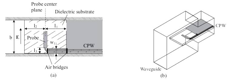
In addition to the ridged waveguide-based designs, there exist other transitions aligned in the longitudinal direction of the waveguide enabling easier construction. In this thesis, two new waveguide-to-CPW transitions aligned in the longitudinal direction of the waveguide have been designed. The first one uses a rectangular probe (Figure 2.1) perpendicular to the waveguide axis.
Figure2.1 - Novel rectangular waveguide-to-CPW transition based on a rectangular probe: (a) a top view and (b) an overview
The second one is based on the use of a fin-line taper and slotline radial stub (Figure 2.2). The designs have been tested with X-band (8.2-12.4GHz) back-to-back transitions.
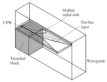
Figure2.2 - Novel CPW-to-rectangular waveguide transition using a fin-line taper and slotline radial stub
The measurements have shown the transitions to be low-loss over the full waveguide frequency band. The measured insertion and return loss for the transition in Figure 2.1 (substrate with ɛr=2.33) are less than 0.5dB and more than 17dB (over a 40% bandwidth), respectively. The transition in Figure 2.2 has been tested with two different substrates ( ɛr=2.33 and 10.8). An insertion and return loss of less than 0.4dB and more than 16dB (over a 40% bandwidth), respectively, are measured for the low-permittivity substrate. Values for the highpermittivity material are less than 1.0dB and more than 10dB, respectively, at 8.2-12GHz (over a 36% bandwidth). The transition design (Figure2.1) has also been used successfully in the LO transition (90-140GHz) of a submillimetre-wave mixer. These transitions provide a practical and reliable alternative for millimetre-wave applications. The simple design, unilateral circuit structure, easy fabrication and suitability for different materials make these convenient for integration of MMIC designs with waveguide systems. Both designs work without air bridges if a proper waveguide housing is used.
3. Waveguide Backshorts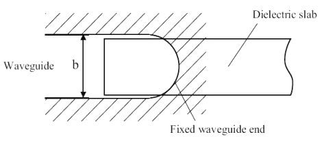
Figure3.1 - New tunable noncontacting waveguide backshort. It is based on a dielectric slab pushed into the waveguide through a hole in a fixed waveguide end. As the slab is moved the electrical length of the waveguide changes and, thus, the phase of the reflected wave changes too
It is based on a fixed waveguide short and movable dielectric slab, which is used to adjust the effective phase constant of the wave in a waveguide section. The structure offers a simple design and fabrication. The simplicity makes it also reliable and low-loss. This design is not sensitive to alignment errors. Furthermore, the in-band resonances, which are possible with the noncontacting backshorts as discussed above are avoided in this structure by using a thin quartz slab and narrow guide channel. In this way, only small alignment errors are possible. Measurements of a W-band backshort show a return loss of less than 0.21dB (VSWR>82) over the entire waveguide frequency band. This backshort gives most accurate adjustment. For example, at 92.5GHz (centre frequency of the W-band) a 10-μm tuning distance corresponds to a 1.7º shift in the phase of the reflected wave in case of the other backshorts whereas in the case of the tested new backshort this corresponds to a phase-shift of about 0.37º. This means an almost 4.6 times more accurate tuning capability at this frequency. This is a great advantage for submillimetre-wave applications. A disadvantage, which may limit the use in some applications, is a large and slightly nonlinear phase variation as a function of frequency. For a tuning distance corresponding to a 360º shift in the phase at 92.5GHz the phase variation over the frequency band is close to 1080º.
4. Bias T-Coupling of Bias to RF Circuit
Devices based on semiconductor components often require dc voltage and for that a biasing network which has a negligible effect on the RF performance of a device. For instance in mixers, a
low-loss and wide-band structure is preferred in separating the dc bias and IF signal. The biasing network, bias T, can be either an integrated part of the device or a stand-alone component.
Basically, it is a diplexer formed by a low-pass and high-pass filter.
A coaxial line-based bias T has been realised. It has been designed for higher IF frequencies, around10 GHz. Figure 4.1 shows one half of the bias T.
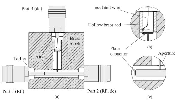
Figure4.1 - Coaxial line bias T: (a) cross-section, (b) blow-up of the RF block, (c) blow-up of the dc block and T-junction
It has two 45-Ω coaxial lines as band-pass filter sections, which was found to give adequate frequency coverage in this case. Here the dc block capacitor is placed in the first element of the band-pass filter. The bias T has been tested at 1-17GHz. The use of the coaxial line structure has provided a very low-loss, wide-band operation with a high return loss. The insertion loss is less than 0.5dB at 3-16GHz (fractional bandwidth of 137%). The return loss is more than 20dB from 4.2 to 15GHz and more than 30dB from 5.2 to 14.1GHz. At the latter range, the insertion loss is about 0.1dB. The measured RF isolation is more than 30dB over the whole measurement frequency band. When comparing the results to those (insertion loss of 0.5dB and return loss of 20dB at best) of the bias circuits discussed above, the insertion loss is extremely 25 low and the return loss is very high. This bias T can also be designed to provide a proper IF match as an integrated structure.
5. Schottky Diode Waveguide Mixers
As mentioned earlier, the mixer is often the first element in a millimetre- or submillimetre-wave receiver. Furthermore, the most common mixing element is a GaAs-Schottky diode. Main reasons
are its ability to provide efficient performance also at room temperature, easy usage, and a wellcontrolled GaAs fabrication process. GaAs diodes suitable for terahertz applications are already
commercially available [76]. For reliability planar diode chips are currently preferred over the whisker-contacted ones. They have also produced comparable mixing performance. This thesis
includes the design and construction of two different Schottky diode mixers.
In this thesis work, a subharmonic waveguide mixer at 215GHz, has been designed within an international ESA project as a study of possibilities of future millimetre- and submillimetre-wave receivers (both open-structure and waveguide types) based on European Schottky diodes. The main goal was to develop European single and anti-parallel Schottky planar diode chips. The diode development work has been carried out at Technical University of Darmstadt (TUD). These chips have a special quasi-vertical structure which was designed to combine the benefits of earlier planar and whisker diode chip structures. During the design of the subharmonic mixer, based on a chip with an anti-parallel pair of diodes (APD), the diode chip fabrication process was in a strong development phase. Especially, yield and uniformity of the process was not good at the time. This produced additional difficulties to the mixer construction. However when compared to other subharmonic waveguide mixers operating at the same frequency range very satisfactory results were obtained. The noise temperature (3500K, singlesideband) is about 3.6 times higher than the lowest one (490K, double-sideband). However, the conversion loss (9.2dB, single-sideband) is comparable to the other ones reported. Also the LO power consumption is similar. The non-uniformity also caused that instead of a two-tuner structure (planned in the early project phase) a four-tuner one was selected for efficient match of the APD chip. This was the first time these diodes were applied in a mixer. The work produced 27 valuable information on the use of this type of diodes for mixer applications. Especially, it showed that these diodes are usable for millimetre- and submillimetre-wave mixers with further improvement of the diodes. Since then the structure of the diode chip and its fabrication process have been further developed by TUD.
6. Conclusions
This thesis work is based on seven scientific articles covering different millimetre- and submillimetre-wave receiver front-end circuits and components. As a result of the work, new circuit
structures are available for millimetre wave designers to construct devices with improved performance, easier designing, easier fabrication, better reliability, or with possibility for new
circuit implementations.
Two new waveguide-to-CPW transitions have been invented and developed. By designing and testing X-band transitions, these structures have shown to have a low-loss performance over a wide band (fractional bandwidth of>40%). These are new practical alternatives for future applications. Due to their simple design, unilateral circuit, and easy fabrication, they are suitable for integration of MMIC designs with waveguide systems. One transition has already been applied in a submillimetre-wave mixer.
For tuning of waveguide devices, a new adjustable waveguide backshort has been invented and developed. It has a performance competitive with the best ones published. It offers several
advantages for millimetre- and submillimetre-wave devices: low losses, large bandwidth, most accurate adjustment, easy design and fabrication, reliability, and insensitivity for alignment errors.
A stand-alone, coaxial line-based bias T has been designed, constructed, and measured. It provides a wide-band, low-loss performance suitable for, e.g., mixer IF outputs.
Two Schottky diode waveguide mixers have been designed, constructed, and measured. One of these is a subharmonic millimetre-wave mixer at 215 GHz utilising European quasi-vertical
Schottky diodes. During the project this work has produced valuable information for the diode
manufacturer and has shown the ability of these diodes for high-frequency applications. The other mixer is a fifth-harmonic submillimetre-wave mixer, which has been designed for instrumentation used in antenna test facilities at 500-700GHz. It was designed to offer an easy usage in the antenna test system. It has been in use in a phase locking system of a backward wave oscillator.
A planar diode chip characterisation procedure has been developed and tested. The procedure provides millimetre wave designers with the results of a variety of extensive measurements together with the parameter values of a simple equivalent diode circuit.
Future research topics are the development of a stand-alone waveguide impedance tuner based on two backshorts invented here, testing of the 5th-harmonic mixer at a wider frequency range,
extraction of a more specific diode model from the characterisation results, characterisation of lowseries resistance varactors, application of the backshort and characterised diodes in construction of a submillimetre-wave mixer, and construction of a microelectromechanical systems-based waveguide impedance tuner with the invented transitions.