Главная страница ДонНТУ
Портал магистров ДонНТУ
Автобиография
Автореферат
Перечень ссылок
Индивидуальное задание
Отчет о поиске
Электронная библиотека
ABRASION
S.C.Black, V.Chiles, A.J.Lissaman, S.J.Martin. Principles of Engineering Manufacture. Third edition, London: Arnold, 1996. - P.372-373;p.376-380.
Introduction
The machining of materials using abrasive material is of increasing importance, not only in the engineering industry, but in many other industries. The processes used produce well controlled surfaces of high finish, and tight tolerances are possible. In addition very hard materials can be machined.
Unlike most cutting processes, in abrasive machining the individual cutting edges have a random distribution and orientation. Since the panicles providing the cutting edge are small, depth of engagement must similarly be small, and tiiese factors result in variable chip fonnation, since any individual grain may encounter the work witJi positive, zero, or in most cases negative rake angle. Thus particles may merely deform the surface, may plough into the surface, or may form chips. Since only a proportion of the grains actually cut, and the others absorb energy without cutting, the energy required is many times higher than cutting for a similar material removal, and there is considerable heat generation.
Grinding
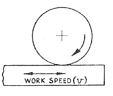
By bonding with an appropriate bonding agent, the abrasive material may be formed into an axiaUy-symrnetric wheel, balanced for high-speed rotation. The grinding processes using such wheels have a geometry of chip formation similar to that of milling, with the grit edges which project from the surfaces of the wheel acting as small cutting teeth, but with random cutting angles. When cutting on the periphery of the wheel, Figure 1, chip formation occurs under similar geometrical conditions to up-cut or down-cut milling, depending upon the direction of work speed relative to the direction of wheel rotation. When grinding on the face of the wheel, Figure 2, the geometrical conditions are similar to face milling.
 Figure 1 - Surface grinding on wheel periphery
 Figure 2 - Surface grinding on wheel face
The principal differences between the cutting action of grinding, and of milling, lie in the following:
1. Grinding grits are sufficiently hard to cut fully hardened steels of the order of 850 HV.
2. The cutting angles of the grits have a random geometry.
3. The pitch of the grit cutting edges is much smaller than the pitch of milling-cutter teeth.
4. The size of the chips cut is very small for grinding, compared with milling.
Any serious study of the grinding process is helped by examination of wheel structure, and of grinding swarf, under a low-power microscope. If a measuring microscope is available the approximate sizes of the grits, and of the chips cut, can be determined. A wide strip of transparent adhesive tape, wrapped sticky side outward round a steel rule and then held in the stream of sparks produced by grinding, may be used to collect a representative sample of the chips.
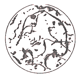
 Figure 3 - Grinding chips (x30 magnification), surface grinding mild steel on aheel periphery, wheel - A 46 L4 V
 Figure 4 - Grinding chips (x30 magnification), surface grinding mild steel on wheel face, wheel - A36 G 10 V
Figures 3 and 4, based upon microscopic examination of grinding swarf, show the form of the chip produced when surface grinding on a horizontal-spindle machine as compared with the longer chip formed when grinding on a vertical-spindle machine. The small spheres are chips that have coiled up and fused together.
Force and power in grinding
Cutting speeds for grinding are always high, the upper limit being imposed either by the safe centrifugal stresses of the wheel or by the upper limit of rotational speed of the spindle employed. Vitrified wheels may be used up to about 1800 m/min; elastic bonds may be used at much higher speeds, up to 4800 m/min for abrasive cut-off wheels. For the internal grinding of small bores cutting speeds may not exceed 760 m/min due to the speed limitations of belt drives and bearings. A 10 mm diameter wheel must rotate at approximately 25 000 rpm to achieve this cutting speed. Bearings which operate up to speeds of 100000 rpm have been developed, but the bearing loads must be very light and special driving arrangements are necessary; compressed air-turbine drives achieve this.
Cutting forces in grinding are difficult to measure and at present it is possible only to estimate the forces which act on the individual grits. The same basic mechanics may be applied to the grinding process as are applied to single point cutting. The force acting on a grit in the direction of its velocity is given by:
T=Kc×area cut
It is difficult to obtain accurate values of the cutting force on a grit, or of the cross-sectional area of the chip cut. The sections of the grooves cut by individual
Grits will vary in shape due to the random geometry of the grits, and any attempt to find the value of the maximum chip thickness, and hence the maximum force on a grit, is necessarily approximate.
The following expression for chip thickness when surface grinding has been derived:

where v = work speed, m/min.
V = cutting speed, m/min.
C = the number of effective grits per mirr of grinding wheel surface.
r = ratio of width to depth of a groove cut by a grit.
d = depth of cut, mm.
D = wheel diameter, mm.
C is measured by rolling the grinding wheel on a piece of smoked glass and counting, under a microscope, the marks left where grit points pierce the smoke film.
r is measured by taper sectioning of the ground workpiece so that the ratios of width to depth of the grooves cut by the grits can be estimated with reasonable accuracy.
It is possible to verify this expression for chip thickness as follows.
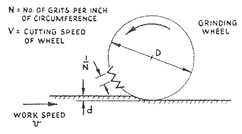
Consider a section through a grinding wheel in a plane normal to the axis of rotation, in which grits are imagined to lie with points projecting as indicated, Figure 5, spaced l/N mm apart, where N is the number of grits per mm of the section circumference. By analogy with milling, the maximum chip thickness is given by, t = 2fg(d/D)0.5, where fg is the feed of the work per grit and t a uniform thickness across the full width of cut. It can be shown very simply that fg, is given by v/NV, so that for surface grinding.

 Figure 5
Consider the area of metal removed across a wheel of face width s at the position of maximum chip thickness.

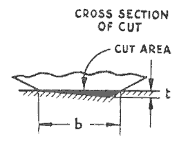
This area is, in effect, removed by a succession of grits and Figure 6 represents a possible condition for the metal removed by a single grit. The area of the cut at maximum chip thickness is tb/2.
 Figure 6 - Typical cross-section cut by a grit
Although the grits have a random geometry there are laboratory methods which enable the average ratio (r) of width b to depth t of the cut to be estimated from a grinding test.
By substitution of b = tr the cut area shown in Figure 6 becomes t2r/2.
Total area of metal removed across the wheel face depends upon N and s; the total area removed is therefore
Nst2r/2 (3)
Equating (12.2) and (12.3)
 but N2=C, by definition; hence

The result clearly indicates the very small magnitude of the chip thickness which occurs when grinding. The depth of cut specified is about 10 times that used for finishing cuts on precision work, hence values much lower than the one determined can be expected for such operations. The very low value of chip thickness then occurring is obviously related to the high quality of surface finish produced by precision grinding operations.
The following data relating to the magnitude of forces and power which occur when precision grinding, has been extracted from a research paper by Grisbrook (1960):
Cutting speed 525 m/inin
Work speed 10.98 m/min
Width of cut 12.7 mm
Depth of cut 0.0076 mm
Material cut, hardened steel of 800 HV
Wheel, WA 46 JV
Grisbrook developed a dynamometer for measuring the horizontal and vertical forces acting on the workpiece during a surface grinding operation. For the conditions quoted, the tangential force at the wheel was approximately 62.3 N, varying slightly with the amount of grinding done since the previous dressing of the wheel.
From estimates of the area of contact between wheel and work, and from values of C for 46 wheel, it is probable that some 18 or so grits would be cutting at one time and that the average tangential force/grit would be about 3.47 N.
It is most unlikely that the force is so evenly distributed. A dull grit will have a higher force than average acting upon it if the normal considerations for single point tools apply to grinding.
The metal removal rate achieved under the conditions quoted is given by:


This is a strikingly high value compared with the values for cutting with single point tools, or for milling operations, on steels. It is shown in Grisbrook's paper that the value is almost as high for unhardened steel of 200 HV. For precision grinding of steel the power criterion watts/w does not appear to depend much on the hardness value of the material cut.
Some research workers tend to express the above relationship in terms of specific energy; i.e. the energy required to remove one mm3 of metal, denoted by
Us=Work done/Volume
The units of Us are
Nm/mm3=J/mm3
converted to specific energy units as follows:
Us=89.7 J/mm3
Grisbrook was able to show that the value of Us, falls as the metal removal rate (w) is increased by an increase in work speed or in depth of cut, i.e. chip thickness (t) increasing. This fact should be compared with the observed fall of specific cutting pressure (P) with increase of chip thickness known to occur for single point cutting.
A fall in the value of Us as the metal removal rate is increased means that the power requirements for grinding at heavy metal removal rates will be lower than the 89.7 W/mm3/s determined above, and an average figure of 30 W/mm3/s is about right for steels. The size of motor provided on a modern grinding machine reflects the high power requirement of the grinding process. One theory put forward to explain the rise in Us which accompanies a fall in chip thickness is that the tangential force on the wheel contains a fairly large element of friction due to the nibbing of grits on the workpiece. The frictional element does not fall as the chip thickness is reduced, hence the energy consumed in removing a unit volume of metal rises.
Биография
Результаты поиска
Ссылки по теме
Автореферат
Индивидуальное задание
Электронная библиотека
Главная страница ДонНТУ
Портал магистров ДонНТУ


