┴╚┴╦╚╬Ď┼╩└
Finite element analysis of bending occurring while cutting with
high speed steel lathe cutting tools
Abdullah Duran, Muammer Nalbant
(Mechanical Engineering
Department, Technical Education Faculty, Gazi University, Ankara, TeknikokuIIar,
Turkey)
The bending which occurs on a cutting tool during machining on a lathe
affects tool life, surface roughness and dimension correctness. In this
research, the bending which has been calculated by Castigliano theorem has been
compared with the bending obtained by finite element method. Under the constant
cutting conditions, material C1060 has been machined with high speed steel (HSS)
lathe cutting tools having 60, 75 and 90 of cutting edge angle. It was
determined by using ANSYS finite elements program that the bending of the
cutting tool generated by the forces, which varied between 1360 N and 1325 N and
occurred during cutting, varied between 0.039958 and 0.04373 mm. According to
the results, it has been observed that the bending that was calculated by
Castigliano theorem and that varied between 0.03542 and 0.034505 mm was almost
the same with the bending determined by finite elements method.
1 INTRODUCTION
Various machine tools and cutting tools are used in metal cutting. Cutting
tools for turning can generally be divided into two groups: high speed steels
and cemented carbides. High speed steel (HSS) cutting tools can be subdivided
into three groups according to their manufacture: single, brazed and index able
inserts.
Cutting tool geometry, chip geometry, cutting tool and workpiece material,
cutting speed and cutting fluid are the main factors affecting the metal cutting
process.
Tool geometry, one of the most important factor affecting metal cutting
process, is determined by rake angle, side clearance angle, side cutting edge
angle and back rake angle. Tool geometry is an important factor having influence
on cutting forces and tool life. For an optimum turning operation, correct
selection of cutting parameters as well as the length of tool holder extending
from its post are essential. That is because, incorrect selection of cutting
parameters leads to rapid tool wear, breakage and plastic deformation. This
increases machine tool idle time due to the changing of damaged cutting tools
and causes some other problems such as poor surface quality and wrong workpiece
dimensions. This, in turn, increases the overall cost.
Determination of cutting parameters through conventional methods is mostly
not possible. Approximate solution methods giving very close results to those
obtained by the experimental work are appealing as they are easy to use and
there is no necessity to carry out costly experimental work. Parallel to the
development in the computer technology, finite element analysis (FEM) method,
one of the approximate solution methods, has been increasingly used. Finite
element method gives very close results to the real values and, therefore, it is
now a well accepted numerical method.
In this study, deflection of HSS cutting tool during turning was
investigated using ANSYS version 5.4 program based on the tool length extending
through the tool post. The deflection of the tool was also calculated using
Castigliano theory and the results were compared to those obtained using ANSYS
program.
2 BASICS OF THE METAL CUTTING2.1 Cutting process
Metal cutting is a complex physical phenomenon which involves elastic and
plastic deformation, intense friction and heat, chip formation and cutting tool
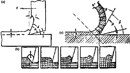
wear. In order to effect cutting action, the cutting tool (as shown in Fig.
1(a)) is forced against the workpiece and is moved relative to the workpiece. As
the result, the workpiece is initially deformed elastically (Fig. 1(b)) and when
the workpiece_s yield strength is exceeded plastic deformation occurs. Plastic
deformation leads to chip formation (Fig. 1(c)). The formed chip leaves the
workpiece through the cutting tool rake face. The flow of the chip occurs in
various ways depending on the workpiece properties and cutting conditions.
 Fig. 1 ľ Chip formation process.
2.2 Cutting forces
The necessary chip formation force required to overcome the developed
stresses during chip formation process can be divided into three components:
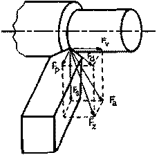
cutting force (Fs), feed force (Fv) and radial force (Fp).
Cutting forces developed during turning are depicted in Fig. 2.
 Fig. 2 ľ Cutting forces acting on the cutting tool during
turning.
Cutting force (Fs) acts against the workpiece turning motion and
forces the cutting tool downwards perpendicular to the workpiece axis. Feed
force (Fv) acts parallel to the workpiece turning axis and is in the
reverse direction of the feed. Radial force (Fp) acts perpendicularly to
the machined surface and forces the cutting tool backwards.
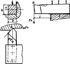
If a cutting tool fixed on the tool post is considered a cantilever beam as
shown in Fig. 3, the deflection of the tool ( ) due to Fs force should be ideally zero during cutting.
 Fig. 3 ľ Representation of the cutting tool as a cantilever
beam.
2.3 Castigliano theory
According to Castigliano theory, partial derivation of the total internal
stress energy with respect to the one of the applied external forces gives the
displacement of the point of applied force in its application direction. The
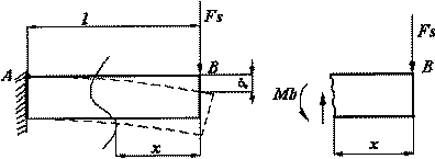
displacement of the equal cross-sectioned beam at point B (Fig. 4(a)) under
Fs force can be found using Castigliano theory.
 Fig. 4 ľ Single side cantilever beam
The bending moment at any point of the beam in Fig. 4(b) can be found using
the following equation:
 If the M moment changes along the beam, internal stress energy
developed as the result of basic bending moment in the beam then dx
length element strain energy is found using
 The total strain energy is calculated in the following way:
 The bending in the beam (
 ) can be
found in the following form:

2.4 Finite
elements
In finite elements method, it is assumed that a part is divided into so many
small parts. This method is, therefore, called finite element method. The main
idea in finite element method is to solve a complex problem by replacing it with
a simple problem. By using the existing mathematical methods, in practice real
or approximate solutions cannot be found for many problems. However, finite
element method can be used to find approximate solutions for these problems. In
finite element method, the solution zone is composed of adjacent sub parts which
are called finite element. It can be assumed that these sub parts are held
together by nuts and screws. It is also assumed that when the bonding is
removed, the sub parts are separatedů


 ) due to Fs force should be ideally zero during cutting.


 ) can be
found in the following form:


 ) due to Fs force should be ideally zero during cutting.


 ) can be
found in the following form:
