
A Comparative Investigation of Electrical
Parameters for Fault Detection and Condition
Monitoring in Induction Motors - Stator
Winding Current and Electromagnetic Flux
XVII International Conference on Electrical Machines ICEM 2006
Abstract—This paper presents a comparative investigation on the usefulness of the electromagnetic flux monitoring approach in comparison with the classical motor current signature analysis approach when aiming to identify various faults in cage induction motors. The research for evaluating the ability of the chosen parameters in fault detection and discrimination is performed on a 35 kW cage induction motor. The relevant fault signatures of the studied diagnostic media are issued both from measurements and from two-dimensional numerical electromagnetic field simulations at steady state. Based exclusively on data obtained from simulations, a study of the modifications brought by various stator winding designs to some of the asymmetrical air-gap electromagnetic flux density harmonics responsible for the detection of various faults is carried out. The studied faults are an inter-turn short circuit in the stator winding, rotor-cage related faults (bars breakage), eccentricities (static and dynamic) and a bearing failure.
Index Terms—stator current, electromagnetic flux, fault diagnosis, induction motor.
I. INTRODUCTION
In general, on-line condition monitoring and diagnostics
require the sensing and analysis of signals that contain
specific information, which is characteristic of the
degradation process, problem, or fault to be detected. In this
respect, measurements of signals such as: currents, voltages,
electromagnetic magnetic flux, speed, torque, vibrations and
temperature can supply relevant fault information. Current monitoring is the method that is most applicable in industry but is also known that the current spectrum is influenced by many factors including: electric supply, static and dynamic load conditions, noise, machine geometry and fault conditions and these conditions may lead to errors in fault detection. Moreover, when a commercial diagnostic system has to operate between a few kW up to MW range of different designs and driving a wide range of mechanical loads, the diagnosis from sensing only the current and its subsequent analysis becomes much more complex than it at first appears [1].
An electric machine, by definition, produces electromagnetic flux. Based on the fact that any small unbalance in the magnetic or electric circuit of an electrical machine is reflected in some of the transmitted fluxes, the magnetic flux monitoring may be efficiently used as an additional or alternative mean to the widely used stator current monitoring. Faults, such as turn-to-turn winding shorts, unbalanced supply voltages or rotor-related ones create greater asymmetries and increase in amplitudes of the frequency components associated with such particular phenomena are expected to reflect these asymmetries.
II. NUMERICAL MODEL FOR FAULT SIMULATIONS
This work uses field analysis in the attempt to provide an
accurate evaluation of the magnetic field distribution for the
test machine. The finite element analysis is a flexible tool
when studying faulted electrical machines as practically all the
electromagnetic faults can be analyzed using the same basic
tool. When the results provided by the simulation tool are
correctly verified by the experiments, at least from a
qualitative point of view, it becomes realistic to claim that, if a
monitoring system cannot detect and diagnose an artificial
fault from the virtual measurement signals, it hardly works
with real electrical machines, either. In the present work, the magnetic field in the core of the machine is assumed to be two-dimensional. The threedimensional end-region fields are modeled approximately using end-winding impedances in the circuit equations of the windings. A more detailed view on the electromagnetic model used in our simulations is to be found in [2], and a description of the fault implementations in the numerical simulations is described in [3].
For fault detection purposes, we are more interested in qualitative than exact quantitative results i.e. more interested in detecting how the monitored parameter behaves as a function of time and not so much in magnitude. In this respect the finite element meshes to be used can be relatively sparse, as long as the geometric symmetry is the same as for the faulty machine and the time dependence of parameters is modeled properly.
III. STUDIED FAULT INDICATORS AND SIGNATURES
For sensing the electromagnetic flux in various machine
locations, the following search coils were studied (see Fig. 1):
- internal search coil mounted around one stator tooth (“1”); both in simulations and experiments,
- external search coil formed of 200 turns with its length equal to the axial length of the machine and width equal to 2 pole pitches (“2”); both in simulations and experiments,
- search coil formed of 200 turns mounted at the non-drive end (“3”); only in experiments,
- search coil formed of 300 turns mounted internal around the motor shaft (“4”); only in experiments,
- search coils sensing the electromagnetic flux harmonics of order “p+1” (“5”) and “p-1” (“6”); both in simulations and experiments.
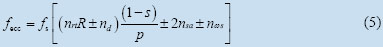
The external search coil placed over 2 pole pitches and the ones purposed to sense the harmonics of order “p±1” were chosen bearing in mind that in a healthy machine the symmetry forbids the flux going through these search coils (the magnetic field of a healthy electrical machine is periodic from one pole pair to the next one) but in a faulted machine such a flux exists. The electromagnetic flux harmonics of order “p±1” determined by analytical means and are of the following form [4]:

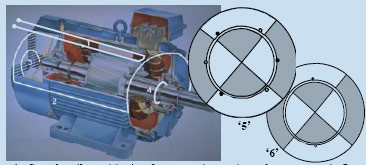
Fig. 1. Search coils positioning for measuring various electromagnetic fluxes.
- inter-turn short circuit reflected in the electromagnetic flux [5]
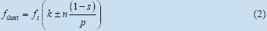
- broken rotor bars reflected both in the electromagnetic flux and stator current [6,7]
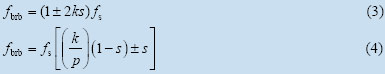
- dynamic or static eccentricity reflected both in the electromagnetic flux and stator current [8]
IV. EXPERIMENTAL AND SIMULATIONS RESULTS
The test cage induction motor described in Table I was fed
from a PWM inverter having a switching frequency of 3 kHz.
A DC generator was used for loading the motor. The currents,
voltages, power and supply frequency, were measured using a
wide band power analyzer. The measurements and simulations
were carried out for three different load conditions (no-load,
half-load and full-load). The current and voltage waveforms
were recorded with a transient recorder. The sampling
frequency was 40 kHz and a typical number of samples was
20000. The measurements were carried out only for the
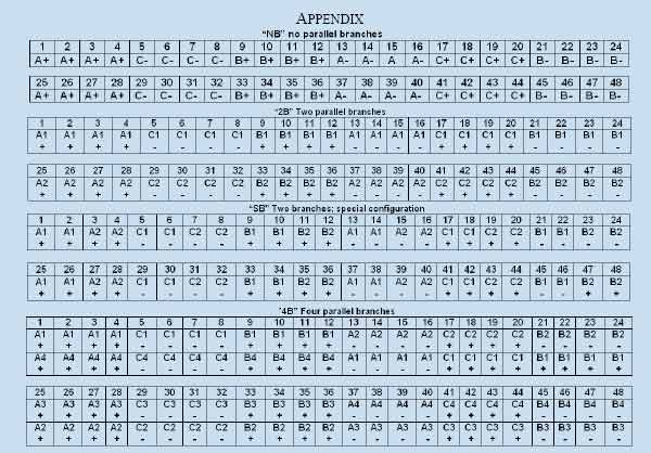
original stator winding topology consisting of 2 parallel
branches (“2B”). The Appendix describes all the studied stator
winding configurations. The tests for the inter-turn short
circuit were carried out only at half-load and no-load
operation points. 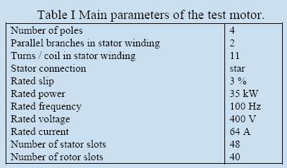
A dynamic eccentricity of 33% was obtained by fitting nonconcentric support parts between the shaft and bearing. In order to create an artificial static eccentricity, the inner diameter of the motor end-shields was decreased about 0.6 mm (the size of the machine air-gap is 0.8 mm). Both endshields were then shifted in the same direction for obtaining a static eccentricity of around 30 %. The rotor cage failures were artificially obtained by drilling holes in the rotor bars and a bearing failure was created by machining a rectangular window in the bearing outer race.
A. Broken rotor bars
Current monitoring
A rotor-cage related failure is reflected differently for motors equipped with various stator winding configurations. The distortions according to Eq. 3 are to be found in all of the studied cases but the ones according to Eq. 4 stand only for the motors equipped with a stator winding configuration of type “2B” and “4B”.
However, the new frequency sideband components given by Eq. 4 provide a precise signature of the rotor-cage fault which is not the case for the ones given by Eq. 3 that may also appear due to pulsating loads, interactions between the motor and the train equipment and particular rotor designs [9]. Fig. 2 is meant to offer an example of the previously mentioned facts.
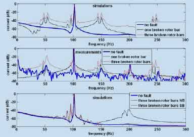
Fig. 2. Frequency spectra of the stator winding branch current.
Electromagnetic flux monitoring
At least for a motor operation at full and half-load, the studied rotor-cage related faults were reflected in well-defined associated fault frequency components (given by Eq. 4) in all of the studied search coils. This is in opposition with the results obtained from the case of the branch current monitoring where a cage-related failure was reflected in this manner only for those motors equipped with a stator winding configuration of “2B” and “4B”. In this respect, the benefits of using search coils for detecting rotor-cage related failures become obvious.
Fig. 3 presents the frequency-domain representation of the voltages induced in the “p-1” search coil during a rotor cage failure both in simulations and measurements.
In a motor equipped with stator winding configurations of “NB” and “SB” type, a rotor cage-related failure produces additional side-bands characterized by higher amplitudes than the corresponding ones sensed in a motor equipped with stator winding configurations of “2B” and “4B” type.
B. Inter-turn short circuit
Current monitoring
Based on measurements, no new frequency components in the line current spectra appeared as a consequence of the fault in the stator winding of the test machine.
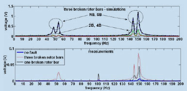
Fig. 3. Frequency-domain representation of the voltages induced in the “p-1” search coil.
For this fault, only a rise in the amplitude of the 3rd harmonic component and of the fundamental was observed from experiments. This amplitude change was independent of the machine loading. With reference to the case of healthy operation, an increase of around 6 dB independent of the machine loading was found in the amplitudes of the rotor-slot harmonics.
However, one should have in mind that low-voltage motors, and especially, random-wound motors usually have appreciable levels of inherent asymmetries and it may be possible that the residual asymmetries of the motor may lead to the appearance of the third harmonic component in the supply currents, even when no faults are present in the motor.
The simulations were in a relatively good agreement with the measured results. In comparison with similar signatures produced by other faults, the new frequency side-bands produced in the frequency spectrum of the branch currents by the inter-turn short circuit are so small that they may be considered in-existent. The simulations also predicted minor modifications (increment of about 2-3 dB) in the magnitude of the principal slot harmonics and in the magnitude at the fundamental frequency (3.5 dB for “4B” and “SB”, 1.6 dB for “2B” stator winding type).
Electromagnetic flux monitoring
For a machine equipped with winding configurations of types “2B” and “4B”, an inter-turn short circuit does not produce any new characteristic frequency side-bands components to be captured by the studied search coils. The measurements pointed out that the new relevant frequency signatures for detecting shorted turns from electromagnetic flux given by Eq. 2 are not observed in the studied search coils.
Search coil around stator tooth. From the measurements, the only significant changes in comparison with the healthy operation were observed at 500 Hz (10 dB increase at halfload and 6 dB at no-load) and at 900 Hz (10 dB increase both at half-load and no-load). In the high-frequency range, no modifications were found in the amplitudes of the slot harmonics in opposition with the increases of around 6 dB observed in the branch current.
The simulations indicated the difficulty to find clear fault signatures in the motor equipped with stator winding configuration of “2B” and “4B”. However, the changes produced by an inter-turn short circuit to the rotor slot harmonics captured by this search coil were found to be more important (7-15 dB) than the ones found in the branch current (2-3 dB). Fig. 4 presents the modifications sensed by this search coil during an inter-turn short circuit in a stator winding of type “NB” and “SB”.
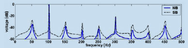
Fig. 4. Frequency-domain representation of the voltages induced in the search coil wound around stator tooth - simulations – half load – inter-turn short circuit in stator winding.
Search coil wound around two pole pitches. From measurements, the only sign of a possible failure was represented by an increment of the fundamental frequency of about 9 dB and 14 dB at half-load and no-load testing, respectively. This is in agreement with the simulations where, for the winding configurations of types “2B” and “4B”, an inter-turn short circuit did not produce any new characteristic frequency side-bands components. In the high-frequency range, the experimental implemented turn-to-turn short circuit is reflected in a relatively slight increment of the rotor-slot harmonics with about 4 dB in comparison with the healthy operation. Fig. 5 presents the modifications sensed by this search coil during an inter-turn short circuit in a stator winding of type “NB” and “SB”.
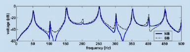
Fig. 5. Frequency-domain representation of the voltages induced in the search coil wound around two pole pitches – inter-turn short circuit – simulations at half load.
Search coil“p+1”. From the measurements, the major increments in the amplitude of the fundamental frequency (12- 16 dB) and in the magnitude of the 3rd harmonic (24 dB) are found higher than those produced by this fault to the other fault indicators. For the winding configuration of “2B” and “4B” type, the simulations also indicate the fundamental and the 3rd harmonic as responsible for carrying important information about an inter-turn short circuit.
Search coil “p-1”. Relying on the measurements, the major changes produced by an inter-turn short circuit to the 3rd harmonic (19 dB both for half-load and no-load operation) are to be noticed. Fig. 6 shows the new frequency side-band components sensed by this coil during an inter-turn short circuit in stator windings of type “NB” and “SB”.
The search coils around the shaft and at the non-drive end of the machine offer useful information about the winding failure especially by capturing the major modification produced in the magnitude of the fundamental frequency component.
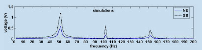
Fig. 6. Frequency-domain representation of the voltages induced in the “p-1” search coil – half-load simulations.
With reference to the healthy operation, these modifications consist of increments in the magnitude of around 13-15 dB (at half-load and no load) for the search coil around the shaft and 20 dB (relatively independent of the loading) for the one placed at the non-drive end of the test motor.
In comparison with the healthy operation, increments in the magnitude of the rotor slot harmonics of around 4 dB (at halfload operation) for the coil placed at the non-drive end and of around 7 dB (both at half-load and no-load) for the one wound around the shaft were found.
C. Static and dynamic eccentricity, bearing failure
Current monitoring Relying on both, experiments and simulations it was observed that the studied static eccentricity and bearing failure does not bring any major modification in the spectral content of the branch current (in simulations, the same conclusion is valid for the case of static eccentricity independent of the stator winding configurations).
Considering only the experimental data, it was also found that the studied bearing failure does not produce any major distortion in the spectral content of the branch current but only increases of around 6-8 dB in the amplitudes of the rotor-slot harmonics relatively independent of the machine loading.
Studying the stator current spectra for both the symmetric and dynamically eccentric rotors it was observed that in the symmetrical condition only the base frequency exists while for the dynamic eccentricity condition, side-band frequencies around the base frequency appear at specific frequencies given by Eq. 5 (see Fig. 7).
An interesting conclusion drawn from the simulations is that the dynamic eccentricity is not reflected in the indications of the branch currents for the cases of “NB” and “SB” stator winding configurations.
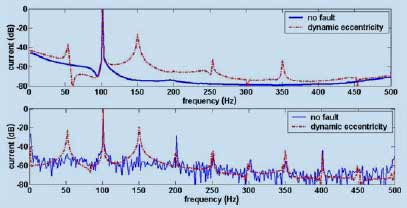
Fig. 7. Spectrum content of the stator winding branch current - dynamic eccentricity – simulations (topmost figure) and measurements at full-load.
Electromagnetic flux monitoring
Search coil around stator tooth. From measurements, it was found that a bearing failure and static eccentricity were not possible to be detected from the indications provided by this search coil. For the case of static eccentricity, the same conclusion was drawn after analysing the simulation data corresponding to the motor equipped with the original winding configuration (type “2B”). Since not even the rotorslot harmonics offer an important hint about static eccentricity, it becomes clear that other means of detecting this type of eccentricity are needed. The dynamic eccentricity was easily detectable both from measurements and simulations corresponding to various winding configurations.
Search coil around two pole pitches. Based on measurements and simulations, only the dynamic eccentricity may be detected via this search coil. In the high-frequency range, the experimental implemented dynamic eccentricity was not reflected very clearly in the magnitude of the rotorslot harmonics (the rotor-slot harmonics magnitude increases were only 2 dB at a full load motor operation in comparison with the healthy operation and smaller for lower loadings). Slightly higher modifications (3-5 dB) are to be found for the experimental implemented static eccentricity independent of the motor loading. However, one may not confidently rely on such modifications to claim the ability to detect a static eccentricity since such modifications are common to other faults/asymmetries (i.e. turn-to-turn short circuit in the stator winding). In the high-frequency range, the experimental implemented bearing failure was very poorly reflected in the rotor-slot harmonics by increasing their magnitudes with around only 2 dB only at half-load in comparison with the healthy operation.
Search coil “p+1”. From the measurements, the static eccentricity is clearly revealed in the information provided by the changes in the magnitude of the following frequency components in comparison with the healthy operation:
- fundamental: increments between 11-14 dB,
- 3rd harmonic: increments between 2-10 dB,
- rotor slot harmonics: increments between 5-15 dB independent of the loading. Based on simulations, Fig. 8 points out the similar behavior of the frequency components sensed in a motor equipped with “NB” and “SB” winding configurations and running under static eccentricity conditions. It is also observed that the magnitude of these sidebands is inversely proportional with the number of parallel branches in the stator winding.
From the measurements, the dynamic eccentricity is clearly revealed in the information provided by the changes in the magnitude of the following frequency components in comparison with the healthy operation:
- side-bands situated at around 50 and 150 Hz (according to Eq. 5) that gradually increase from 6 dB at full-load to 16 dB at no-load,
- rotor slot harmonics: increments between 12-24 dB (fullload), 8-22 dB (half-load), 8-17 (no-load).
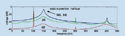
Fig. 8. Frequency-domain representation of the voltage induced in the “p+1” search coil - simulations.
Search coil “p-1”. Relying on the measurements, the static eccentricity is clearly revealed in the information provided by the changes in the magnitude of the following frequency components in comparison with the healthy operation:
- fundamental: increments of around 15 dB (independent of the loading),
- 3rd harmonic: increments between 10-20 dB (getting higher at lower loads),
- rotor slot harmonics: increments between 4-6 dB (independent of the loading).
From the measurements, the dynamic eccentricity is clearly revealed in the information provided by the changes in the magnitude of the 3rd harmonic that are of around 4 dB independent of the loading
-rotor slot harmonics: increments between 14-26 dB (fullload), 12-20 dB (half-load) and 8-20 dB (no-load).
A bearing failure was not possible to be detected from the “p±1” search coils since only a small change in the magnitude of the rotor-slot harmonics (increment of 2-3 dB) in comparison with the healthy operation was found. Moreover, such minor changes in the magnitude of the rotor-slot harmonics were also found for other types of failures, and therefore, such indication is not even suitable for achieving discrimination between them.
Both for the “p+1”and “p-1” search coils, the dynamic eccentricity was easily detectable from simulations corresponding to various stator winding configurations. Search coil wound around the shaft. A search coil purposed to sense the axial flux was found able to indicate a failure in the bearing, this being the clearest mean to observe this fault. However, this signature was found almost similar with the one obtained from the static eccentricity (Fig. 9) that, in terms of apparition of new frequency components, was also invisible in the indications of the previous mentioned search coils. In the high-frequency range, the bearing failure was relatively clearer reflected in the indications provided by this search coil; an increment of around 10 dB in the magnitude of the rotor-slot harmonics at full-load seems to be more important than the similar modifications produced by the same fault and by various faults in other search coil indications. For the halfload and no-load, the same modifications were about 7 and 4 dB, respectively.
The static eccentricity was also reflected in the rotor-slot harmonics by increasing their magnitudes with 8-10 dB at a full load motor operation with reference to healthy operation. For half-load and no-load motor operation points these indications decrease to a level of 4 and 3 dB, respectively. Search coil placed externally at the non-drive end of the motor. This search coil was not able to sense the cases of static eccentricity and bearing failure.
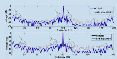
Fig. 9. Frequency-domain representation of the voltages induced in a search coil placed around the motor shaft – measurements – full-load.
V. CONCLUSION
It was found that the detection accuracy of various
abnormalities in an induction machine (especially those
related to eccentric rotors) is enhanced by using the air-gap
mounted search coils sensing the harmonics of order ‘p±1’.
Clearly, some of the abnormalities difficult to be detected by
the classical motor current signature approach (bearing failure,
static eccentricity) have been detected via monitoring the
electromagnetic flux.In most of the cases, our simulation tool has the ability to identify the frequency components responsible for the clear distortion of the electromagnetic flux and stator current waveforms due to various failures.
For motors equipped with stator windings of “NB” and “SB” types, all of the studied faults were reflected in a similar way in the indications provided by various fault indicators.This is important to notice since these configurations are completely different. Therefore, it is concluded that not only the number of parallel branches but also the winding internal connections affects the fault indications.
REFERENCES
[1] W. T. Thomson, “A review of on-line condition monitoring techniques
for three-phase squirrel-cage induction motors–past, present and future”,
IEEE International Symposium on Diagnostics for Electrical Machines,
Power Electronics and Drives, Sept. 1–3, 1999, Gijon, Spain, pp. 3–17.
[2] A. Arkkio, “Analysis of induction motors based on the numerical solution of the magnetic field and circuit equations,” Helsinki, Acta Polytechnica Scandinavica, Electrical Eng. Series No. 59, ISBN 951- 666-250-1, 97 p.
[3] S. Poyhonen, M. Negrea, P. Jover, A. Arkkio, H. Hyotyniemi, “Numerical magnetic field analysis and signal processing for fault diagnostics of electrical machines,” International Journal for Computation and Mathematics in Electrical and Electronic Eng., Vol. 22, No. 4, 2003, pp. 969 – 981.
[4] J. Fruchtenicht, H. Jordan, H. Seinch, Exzentnzitatsfelder als Urache von Laufinstabilitaten bei Asynchronmachinen, Parts 1 and 2, Arkiv fur Electroteknik (German), 1982, 65, pp. 271-292.
[5] J. Penman, H. G. Sedding, B. A. Lloyd, W. T. Fink, “Detection and location of interturn short circuits in the stator windings of operating motors,” IEEE Trans. on Energy Conv., vol. 9, no. 4, Dec.1994.
[6] P. Vas, Parameter estimation, condition monitoring, and diagnosis of electrical machines, Oxford, Clarendon, 1993.
[7] N. M. Elkasabgy, A. R. Eastham, G. E. Dawson, “Detection of broken bars in the cage rotor on an induction machine,” IEEE Trans. on Industry Appl., Vol. IA-22, No. 6, pp. 165–171, Jan./Feb. 1992.
[8] J. R. Cameron, W. T. Thomson, A. B. Dow, “Vibration and current monitoring for detecting air-gap eccentricity in large induction motors,” IEE Proc., pp. 155–163, Vol. 133, pt. B, No. 3, May, 1986.
[9] W. T. Thomson, “On-line current monitoring—The influence of mechanical loads or a unique rotor design on the diagnosis of broken bars in induction motors,” in Proc. ICEM’92, Manchester, U.K., Sept. 1992, pp. 1236–1240.