Speed and Torque Control of a Permanent Magnet Excited Transverse Flux Motor for Direct Servo-Drive Applications
Werner U., Schuttler J., Orlik B.
Institute for Electrical Drives, Power Electronics and Devices
Источник:International power electronics and motion control conference, 11 - 14 September 2004, Dresden, Germany. EPE-PEMC 2005.
Keywords
Adjustable speed drive, Servo-drive, Permanent magnet motor, Transversal flux motor, Modeling, Simulation
Abstract
This paper deals with an innovative method to minimise the cogging torque of transverse flux motors in direct drive applications to achieve an accurate speed control. These approaches are based on calculated optimised current wave forms to realise a torque control as a basis for the speed control.
Introduction
For some years, there has been a strong trend towards drive solutions with direct drives. Direct drives are often realised with high torque motors which, as a rule, represent the slowly running machines. They reach very high torques at low speed. Consequently, the gear can be saved; it increases the complete degree of efficiency and the dynamic properties of the drive system. The aim of this technology is to increase the torque density (Nm/m?) or also the weight bounded torque density (Nm/kg) depending on the load (power, speed). To drive a direct coupled motor-load-system the speed of the direct motor has to be controlled accurately. To realise this accurate control a constant torque of the motor over the whole speed range is needed. This paper presents how the cogging torque of the transverse flux motor (TFM) can be minimized by an optimal current control to reach the required speed control.
The Transverse Flux Motor
Transverse flux motors represent one of these topologies of the electrical machines with high force densities. The form of this electrical machine represents an essential innovation in the use of direct drives. The fulfilment of the requirements in terms of small volume and weight of motors with high torque densities at low speeds plays an important role. The concept of transverse flux machines was developed at the beginning of the 20th century. But due to a lack of appropriate electronic devices and converters the practical use of these types of machines started only many decades later. In the 80ies Prof. Weh from the technical University of Brunswick, as one of the pioneers in this field, has developed new types of machines based on the transverse flux principle. These machines were used as uncontrolled traction force drives.
The availability of intelligent power converters today allows extending the use of transverse flux machines for applications where the control of speed and energy fluctuation is required.
A typical feature of transverse flux machines is the magnetic flux path which has sections where the flux is transverse to the rotation plane and the ring-shaped winding in the stator in which the direction of the current corresponds with the movement direction of the rotor. The innovative design of the flux path combined with the use of new magnet materials lead to very high-performance machines with three to five times higher power densities compared to conventional DC, synchronous and induction machines. This means that a transverse flux machine with the same power rating is reduced in size and weight compared to conventional machines. An additional advantage of transverse flux machines is their higher efficiency. There are two main reasons for this: the reduced copper losses, due to the absence of end-turns in stator winding, and the fact that the magnetic circuit and the electrical circuit don’t share the same space. We have to discern between two different topologies of permanent magnet excited transverse flux motors (TFPM). One topology is the flux concentrating transverse flux motor (fig.1) and the other topology is the flat magnet transverse flux motor (fig.2). The transverse flux motor in flux concentrating configuration can achieve a higher force density but has also a higher amplitude of torque ripples. The flat magnet configuration has a lower force density, but depending on the surface mounted magnets, less torque ripples.
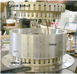
Fig. 1:Two phase TFPM in flux concentrating configuration
At present, the force densities of normal asynchronous motors can achieve up to 20-30 kN/m. Water-cooled and force density optimized high-performance machines can reach 65 kN/m and for a short time even up to 80 kN/m?. The norm for the synchronous machines complies with 40-60 kN/m. Transverse flux reluctance machines can achieve up to 60 kN/m and the water-cooled permanent magnet transverse flux machine yields more than 200 kN/m.
Besides the described advantages there are a few disadvantages of transverse flux machines. These are the ripples in the torque shape, the normal force fluctuation, the low power factor and the complex core design. The torque ripples and normal force fluctuation produce noise and vibrations. There are some kinds of solutions to reduce the torque ripples and the normal force fluctuation. One of them is modifying the geometry for the magnetic path. Furthermore, an appropriate current wave form can be applied to the machine.
In this paper innovative methods are introduced in which a constant torque can be produced by optimized current wave forms in a transverse flux machine. The needed current control for a transverse flux motor will be implemented in a microcontroller and tested on a test bench with a two phase transverse flux motor in flux concentrating configuration and a three phase transverse flux motor in flat magnet configuration. All described methods and control structures can be applied to both kinds of machines.
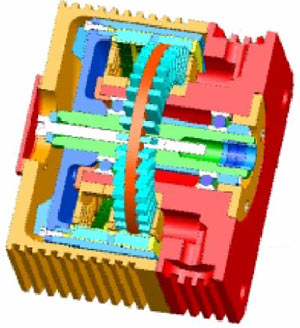
Fig. 2: Two phase TFPM in flat magnet configuration, sketch by Landert
Calculating the optimised current waveforms
Based on its principle, the transverse flux motor has forced points of no torque. The distance of these zero points is one pole pitch. Therefore a minimum of two phases has to be used in a permanent magnet excited transverse flux motor to compensate these points of no torque. The torques of those both phases is added together at the shaft of the motor. To get a cogging free toque both phases have to be coupled with a 90 degree shifted current and a special current waveform is needed, too.
How to get those waveforms is described in the following. A very simple and intuitive method [5] of minimizing the cogging torque of a TFM with two phases is the trapezoid method. The essential principle of this method is based on generating a trapezoid torque wave form which has a cycle of one pole pitch and which is smaller than the maximal possible torque (fig. 3).
There is no need to choose a curve with maximum value (as shown in the example). It is possible to use smaller values. By using an analytical model (described in [5]), it is possible to calculate the corresponding current in this phase on each position of the rotor in order to achieve the required torque wave form. The total torque of both phases forms a cogging free curve at the maximum value of the trapezoids.
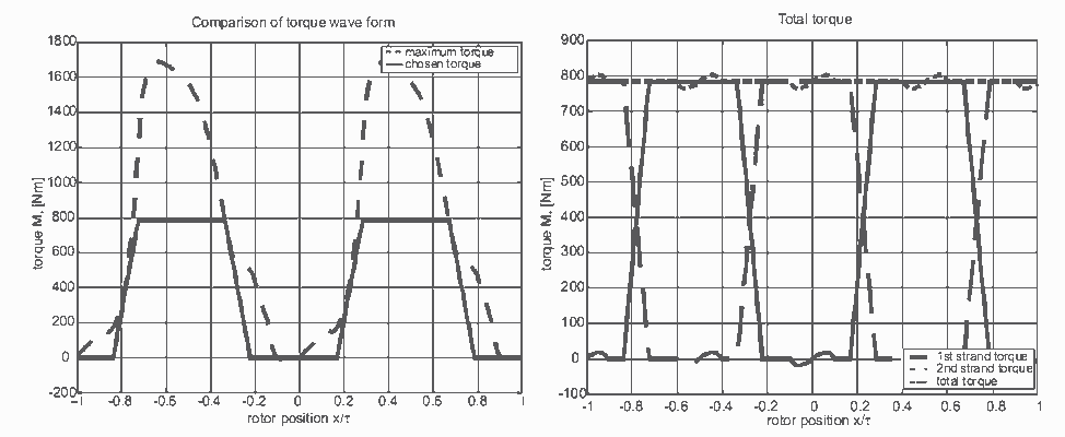
Fig. 3: Trapezoid curve less than maximum torque Fig. 4: Resulting minimized cogging torque
But there are two problems, as it is shown in fig. 3 and fig. 4. Around the point of no torque at rotor position x = 0 the chosen curve cannot be put into effect. The resulting actual wave form influences the wave form of the total torque at the same position. For this rotor position the simple look-up-table approach produces very high current values in this area.
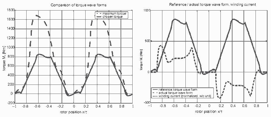
Fig. 5: Modified trapezoid curve; Fig. 6: Realization of reference torque curve
A simple modification of the trapezoid method eliminates both problems. Nearby the point of no torque a zero current is required, resulting in a torque wave form induced by the permanent magnets. At some point the current generation process has to be switched back from this torque wave form to the trapezoid torque curve. This point is selected in order to avoid a step in the total curve. The derivation from the original trapeze can be compensated with the second phase. The results of fig. 5 and fig. 6 can be achieved by application of the modified simple method to the maximal possible torque. It is possible to achieve a cogging-free torque of high level with the modified trapeze method. The used calculation is very simple and makes it possible to apply this in online operation, e.g. in an error-case shutdown scenario. It does rely on the set of characteristic curves and the correct injection of the winding current.
The control structure
The main requirements of a direct drive are a constant torque and a constant speed at every operation point. To reach these requirements for the transverse flux motor an accurate torque and speed control on a basis of a fast current control is needed. Therefore the permanent magnet excited transverse flux motor with reduced torque and current ripples can be used in a direct servo drive application. A control structure based on the calculated transverse flux motor model is presented in fig. 7.
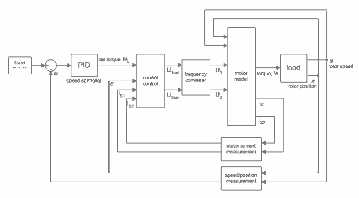
Fig. 7: Structure of the control used in simulation and on microcontroller
In addition a speed control is added to this structure. With the calculated optimised current wave forms and the control structure a minimal cogging torque and a minimal cogging speed as it is shown in fig. 8 and fig. 9 will be expected. Therefore the speed of the motor can be adjusted accurately at every operation point.
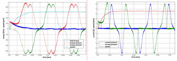
Fig. 8: Simulated total torque at nominal speed Fig. 9: Simulated phase current and speed
To verify the simulation results the control structure of fig 7. is implemented in the microcontroller and different tests and measurements will be done. The test bench with the three phase TFPM described above is shown in fig. 10. The load consists of a short shaft with several rigid, low-friction elements, and a switched-off induction machine (IM). So the controller essentially works with a low rotational moment of inertia with low friction.
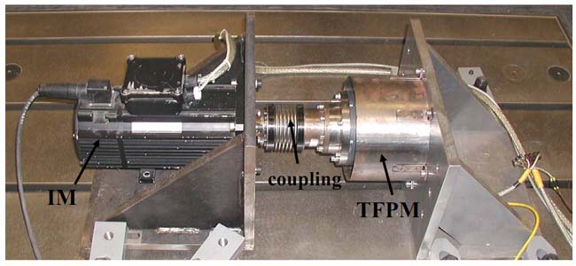
Fig. 10: Test bench with a three phase transverse flux motor in flat magnet configuration
The speed control basically consists of a conventional PI- / PI-(current controller)-cascade, with the addition of a feed forward control of the back e.m.f. In doing so, a largely proportional correlation between armature current and shaft torque is assumed, nonlinear behaviour by saturation, temperature and rotor position dependency is left to the controller as disturbance.
Since always one of the three phase currents / voltages depends on the other two by means of Kirchhoff’s laws, the system can be reduced to two independent phases by transformation calculation. The result can be interpreted as a Cartesian system, in which vectorial calculation is possible.
For this vectorial control principle asymmetries between the three phases are neglected. The structure in fig. 10 does not show the reduction of the rotor position ? to only one periodic region (electrical angle). This approach implicitly neglects asymmetries on a full rotation. So the control can only produce appealing results for a highly accurate symmetric construction. This pre-condition is valid for the 3 phase machine, as it is obvious in earlier measurements.
The correct field position can be derived from the rotor position, as it is true for a synchronous machine, so the current vector will produce maximum torque for a simple offset of 90° (electric. angle). For the single phases this means maximum current at a rotor position in the middle between full pole overlapping and the position between two neighbouring poles. If the absolute value of the current vector stays constant, the phase current in all other rotor positions result in a sine curve.
The detailed structure of the control is pictured in fig. 11. Thick lines depict vector quantities.
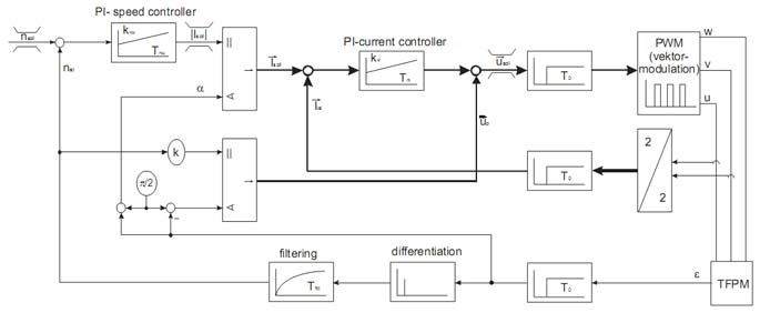
Fig. 11: Detailed control structure implemented in the microcontroller
The control parameters were set to kvw = 5 kg m and Tnw = 15 ms, kvi = 40 und Tni = 5 ms by means of experimental adaption. The proportional factor k and the offset angle of the back e.m.f. were determined by measurements. In the control loop there also are uncompensated communication delays of T0 = 187.5 mcs. The converter can switch between ±325 V d.c. voltage at the output terminals. The speed filter Tfilt is adjustable and was set to 500 mcs in the experiment. The limits were set to nmax = 500 rpm, |Imax| = 12 A and |Vmax| = 216 V (phase voltage), each with an anti-windup mechanism for the integral element of the controller. Not shown in fig. 10 are safety switch-off conditions for the real values and an additional limit for the current-time area for currents above 4 A.
Measurements and Results
Using the system described above one speed step-response was recorded. The various system quantities are given in fig. 12 to 16. Quick and stable control behaviour is shown in the results. The missing compensation of the cogging torque is noticeable in the final steady-state speed, resulting in about 1.5 % deviation. As a result of the uncompensated communication delays the real voltage vector always features a negative angle offset to the desired voltage vector. In the comparison between actual and setpoint value of the armature current this results in a stationary control error. But this does not affect the speed control behaviour.
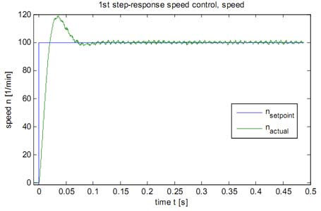
Fig. 12: Step response of the speed control
Fig. 13: Current vector and angle of the speed control
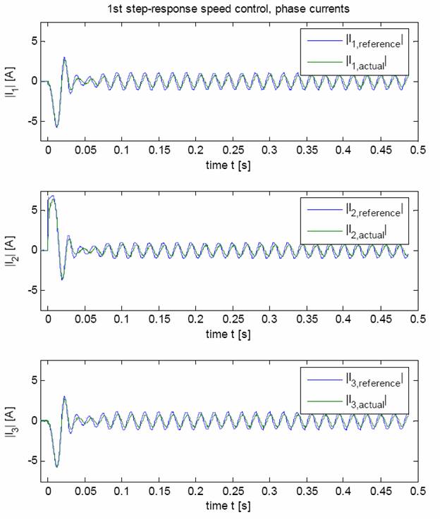
Fig. 14: Current inside the three phases
Fig. 15: voltage vector
Fig. 16: voltages over the three phases
References
[1] H. Weh, H. May: „Achievable force densities for permanent magnet excited machines in new configurations”, ICEM?86, Munich, 1986
[2] H. Weh: „Permanentmagneterregte Synchronmaschinen hoher Kraftdichte nach dem Transversalfluss-konzept“, etz Archiv, vol.10, pp.143-149, 1988
[3] U. Werner, H. Raffel, O. Harling, N. Parspour, B. Orlik: “Strategies to Reduce Torque and Current Ripples of Transverse Flux Permanent Magnet Generators for Wind Turbine Applications”. EPE, Toulouse/Frankreich 2003
[4] M. Vinogradski, U. Werner, B. Orlik: „Genetic Algorithms Used for Geometrical Structure Design of Transverse Flux Permanent Magnet Motors to Optimize the Torque Wave Form“. PCIM N?rnberg 2004
[5] M. Vinogradski, U. Werner, J.Schuttler, T. Petter, B. Orlik: „ Generation of optimized current wave forms for the production of minimized cogging torque of transverse flux motors for direct drive applications “. EPE-PEMC Riga/Latvia 2004
[6] Nurnberger I., Beineke S., Meyer N.: „Hohlwellen-Direktantriebe f?r Handlingaufgaben in Produktionsmaschinen“. Antriebstechnik Bd. 42 Nr.2, 2003
[7] http://www.servax.com/produkte/pdf/wm024/wm_024_d_high_torque.pdf
[8] http://www.servax.com/produkte/high_torque/mtc/massbilder/pdf/9_09_111b_massb_mtc1_145x.pdf
[9] S. Berchten: „Kosten sparen – mit Direktantrieben in Transversalflusstechnik“. Landert-Motoren AG, 8180 Bulach, Schweiz