Effective use of water in a system for water driven hammer
drilling
Goran Tuomas
Division of Renewable Energy, Lulea University
of Technology, SE-97187 Lulea, Sweden
Received 28 November 2002; received in
revised form 10 August 2003; accepted 18 August 2003
ABSTRACT
Drilling with water driven down-the-hole (DTH) hammers is a recently
developed method for competitive production of boreholes. In order to prevent
large amounts of water being used during operation, the drilling fluid is here
directly processed into a quality acceptable for reuse. The effectiveness is
evaluated in well drilling with a mobile prototype water cleaning and
pressurising unit. Especially the presence of abrasive particles in the fluid
can drastically reduce tool life and make the method inefficient. The vital
significance of this relation has called for detailed studies and a process
simulation model for determining particle concentration and size distribution
has been developed. This paper describes the model and how it is applied.
Simulation results of different system configurations are also presented. © 2003
Elsevier Ltd. All rights reserved.
Keywords: Drilling; DTH; Hammer;
Down-the-hole; Particle; Flow; Water; Simulation
1 Introduction
The technique of using water instead of air as an energy carrier to
DTH-hammer tools has been known for years. However, technical difficulties
associated with corrosion, cavitation and wear have made it difficult and/or
costly to put these ideas into practice. This situation began to change in the
early 1990s when the Swedish mining company LKAB started to use water driven
DTH-hammers for production drilling of blast-holes. The use of the hammer-tool
also meant continuous evaluation and improvements of the system, which today is
a highly cost-effective and competitive drilling method. Today, more than
5-million meters of blast-holes have been drilled with the water driven hammer
tool within the Swedish mining industry.
There are many advantages with this
method; the most important are its cost-effectiveness and competitive
performance. The technique offers high penetration rates and low energy
consumption as well as the possibility to drill to virtually any depth (Tuomas
and Nordell, 2000). The working environment is improved since dust is eliminated
and the air is free from oil residues. However, one disadvantage is that a large
flow rate of preferably high quality water is required to drive the hammer tool.
For instance, an ordinary 4-inch hammer-tool requires between 0.2 and 0.4 m3/min
to achieve a competitive rate of penetration. This means that the water should
be recycled when this drilling method is used in locations with limited water
access and/or when waste disposal is difficult to accomplish (Fig. 1).
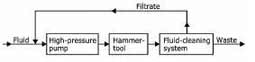
Fig. 1. Principle
flow in a drilling system with re-circulation
The concentration of particles in the drilling water depends mainly on the
actual water flow rate, penetration rate, and the density of the drilled rock.
Mass concentrations (w/w) between 4 and 12% are common for rock drilling with an
ordinary 4-inch hammer. This corresponds to approximately 13-27 kg/min particle
flow, which means that high-capacity cleaning equipment has to be used. The
particle size distribution varies with a certain number of factors. Rock
characteristics, drill bit design and impact energy, are some of them. An
important limiting factor during vertical or inclined drilling is the speed of
the flushing water, since this must be larger than the particles settling speed.
Otherwise the particles will settle in the borehole and will be re-crushed by
the drill bit until the size is small enough to follow the flow. Particles
generated during typical 4-inch well drilling are usually smaller than 1 mm with
mass median sizes (dso) at approximately 0.1 mm.
For the technique to be
successful, the fluid cleaning system must be correctly designed and implemented
since fluid quality directly affects component life. Abrasive particles and/or
aggressive chemical substances in the feed water significantly reduce tool life,
especially when ordinary tools made of hardened steel are used. It is, however,
possible to use tungsten carbide as tool material, but this increases the cost
and this material is, therefore, normally only used in mud driven tools. For
this reason, knowledge of how different water related parameters affect the life
of a given tool or material is of vital importance when designing cost effective
systems.
Interesting data have been obtained from practical use of these
tools, especially within the mining industry where automated drill-rigs produced
millions of meters of 4-inch blast holes. Results from water-analysis and data
of the corresponding tool-life, show that time between repairs corresponds to
approximately 1500 drilling meters in hard rock when the feed water contains
maximum 0.02% w/w solids. The mean penetration rate during these drillings was
0.9 m/min, which gives a total of approximately 6 million piston blows between
repairs, since the piston blow frequency is about 60 Hz. Other experiments have
shown that the life was drastically reduced by large amounts of solids in the
feed water. For example, life less than 100 drill-meters have been measured when
the feed water contained about 0.5% w/w solids (Oderyd 2001).
To evaluate the
possibilities of this system, a complete mobile prototype service unit for use
with low-cost clear-water hammers has been constructed (Tuomas 2001). The unit
includes all components required for efficient drilling, i.e. systems for both
pressurising drilling fluid and particle-fluid separation (by a lamella
thickener and a hydro-cyclone unit) to enable recycling. The prototype unit is
presently undergoing initial operational tests in order to establish the
relation between tool life and particle content in the drilling fluid. System
characteristics for the prototype were estimated by simulations with a process
model, implemented within the Matlab Simulink math package. Particle size
distributions, concentrations, and flows are resolved at strategic locations,
which make the model suitable as a tool for optimisation and development of next
generation systems.
This paper describes the process in the prototype system
and how it is modelled, and discusses the simulated results for different system
configurations. In addition, field test data of the lamella thickeners cleaning
capacity are also presented.
2 Prototype system description
2.1. General description
The process in the prototype system is described in Fig. 2
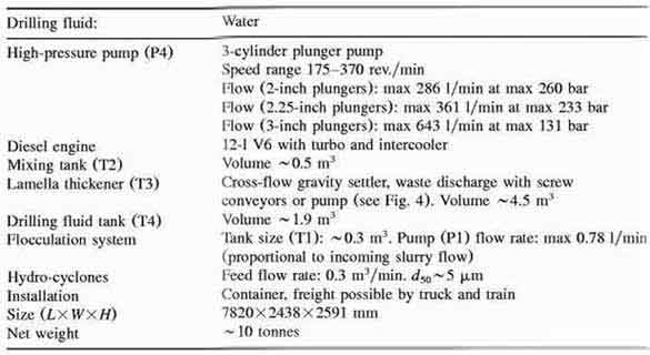
A plunger pump
(P4) pressurises water, which is used for driving the hammer tool and for
flushing the borehole. Particle-contaminated water is returned for cleaning
before re-use. The cleaning process is based on a lamella thickener with a
flocculation system and a hydro-cyclone unit. The equipment was built into a
single container (Fig. 3) for ease of transport and handling. The complete
system is described in more details by Tuomas (2001). Table 1 summarises some
important specifics of the system.
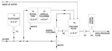
Fig. 2. Schematic flow-chart describing the prototype
process.
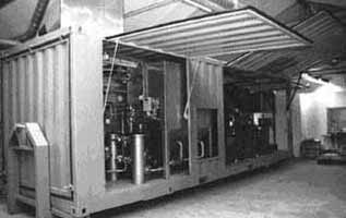
Fig.
3. Prototype system unit.
Table 1.System specification
2.2. Fluid cleaning system
The prototype cleaning system uses gravity sedimentation for primary
separation of particles from drilling water. The lamella thickener is of
cross-flow type, leading to a horizontal flow between inclined lamellas (Fig.
4).
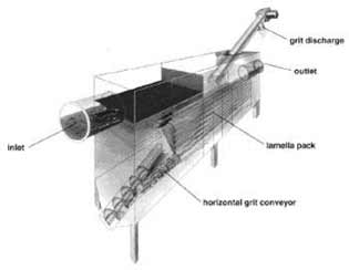
Fig. 4.
The prototype lamella thickener (T3 in Fig. 2). The unit is of cross-flow type
and equipped with screw conveyors for grit discharge.
Particles settle onto the lamella and slide towards the centre of the unit
and eventually reach the bottom of the tank. A horizontal conveyor transports
the sediment towards the end of the settling unit, where another inclined
conveyor removes the waste out of the system. This second conveyor also serves
to dewater the waste in order to achieve low water consumption. The settling
unit is equipped with a pump for sediment removal if the conveyors are
insufficient. Efficiency of sedimentation processes can be significantly
improved by adding a flocculent to the incoming slurry flow. These substances
gather individual fine and colloidal particles into clumps (flocks) that settle
out more easily.
In addition, particle-fluid separation can be achieved with
hydro-cyclones. The idea is to use the hydro-cyclones as an alternative to
flocculation. The hydro-cyclone unit has a dso cut-point below 5 μm (particles
with density 2750 kg/m3 in water). It is designed for a 0.3 m3/min flow and
consists of sixty Ø10mm hydro-cyclones.
3. System process model
A numerical model for simulation of particle flows in the prototype system
has been developed. Mathematical expressions for significant components are
derived, and the whole model is implemented within the Matlab Simulink™ math
package. Results of main interest are the time dependent particle size
distribution functions Ф(s,t) and corresponding volume flow rate functions,
q(t), at different locations in the system. Fig. 5 shows the principle flow
scheme and mathematical descriptions of the different blocks are presented in
the following sections
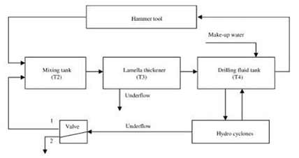
Fig. 5. Principle flow scheme of the process model.
3.1. Hammer tool
The hammer tool block in the model adds particles to the system. This is
mathematically described as:
Φout(s,t) = Φin(s,t) + Φh(s) (1)
where
Фin,(s,t) and Фout(s,t) represent the particle size distributions in the fluid
entering and leaving the hammer tool. Фh(s) represent the particles that are
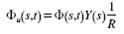
generated during drilling. The Ф-functions also represents the volume
concentration of particles in the corresponding slurry according to
equation:
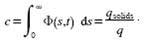 (2)
(2)
where qsolids is the volumetric flow rate
of solids and q is the flow rate of slurry. Фh(s) in Eq. (1) is calculated
as:
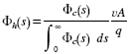 (3)
(3)
where v and A represent the penetration rate
and borehole cross-area, respectively. Фc(s) is a time independent function
which represents the shape of the particle size distribution curve generated by
the hammer tool. The curve used in this study (Fig. 6) comes from laboratory
analysis of a drill water sample, taken during typical rock drilling on ~ 100 m
depth with a 4-inch hammer tool. The shape of Фc depends on various parameters,
such as the actual borehole depth, borehole orientation, flow rate, mineral type
and drill bit design as well. The shape of the curve is, however, assumed
constant in this model. The slurry flow rate, qout, from the hammer block is
assumed equal to the incoming flow rate, qin.
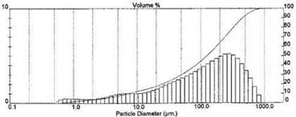
Fig. 6.
Particle size distribution in a drill water sample, taken during drilling with a
4-inch water driven DTH-hammer tool at approximately 100-m depth. The curve is
used to represent function Фc in the described process model.
3.2. Mixing tank and drilling fluid tank
In a tank containing a substance with concentration c, the changed particle
concentration by time is described by a differential equation:
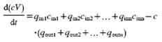 (4)
(4)
where q is the flow, c is the concentration at n number of
intake- and outlet ports in the tank, V is the volume, which may vary with time.
After inserting Eq. (2) into Eq. (4), the equation for a tank with n number of
intakes is derived as:
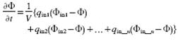 (5)
(5)
where Фin is the particle
size distribution in the fluid entering the tank, qin is the corresponding fluid
flow rate to the tank and Ф is the particle size distribution in the tank. The
model assumes that both the mixing- and drilling fluid tanks are initially
filled-up with clear water. The initial condition to Eq. (5) is, therefore,
Ф(s,0) = 0. The volume in the drilling fluid tank will steadily decrease during
drilling. The reason is that the separation processes in the lamella thickener
and hydro cyclones consume fluid during operation. Opening a water intake at a
low fluid level, and closing it when the tank is filled solves this problem. The
model is designed to work in a similar way. One of the intake flows, qin in Eq.
(5), is changed from zero to a user defined positive value when the tank level V
has reached the low limit, and goes back to zero when the upper limit is
reached.
3.3. Lamella thickener
The lamella thickener (Fig. 4) is designed for a horizontal flow of slurry
between inclined lamellas. Particles settle against the lamella and slide
towards the centre of the unit and eventually reach the bottom of the tank. Fig.
7 shows some principle particle trajectories between two lamellas during steady
flow conditions. Using symbols in Fig. 7, the critical settling speed for a
particle, starting at point (0,y), is calculated by:
 (6)
(6)
where vcr is the critical settling speed, y is the path start coordinate,
U is the slurry flow speed and L is the lamella length. Particles with settling
speed lower than vcr, starting at point (0,y), will go to the overflow (accept),
while particles with a higher settling speed will end up in the underflow
(reject). The actual terminal settling speed for a spherical particle with
diameter d is calculated as:
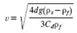 (7)
(7)
where d is the
particle diameter, g is the acceleration, ρs is the particle density, ρf is the
fluid density and Cd is the form drag coefficient. By setting Eq. (6) equal to
Eq. (7) and finding the corresponding particle diameter, the efficiency curve
for a lamella thickener according to Fig. 7 is obtained. To solve this, an
iteration procedure is required, since Cd is a function of the particle Reynolds
number, Re, which besides the viscosity depends on the particle diameter and the
settling speed.
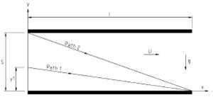
Fig. 7. Principle outline of two particle paths in a
horizontal lamella thickener. Ideally, all particles larger than d2 (belonging
to path 2) will go to the underflow. Particles with sizes d
A commonly used function to describe the efficiency of a particle-fluid
separation process is the Rosin-Rammler formula (Crowe et al., 1998):
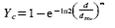 (8)
(8)
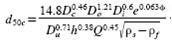
Here parameter Yc denotes the corrected efficiency and is
the probability of a particle with size d to go to the underflow. The parameter
d50c is the cut size of the corrected grade efficiency curve (or corrected
partition curve), and m is a factor that affects the sharpness of the curve.
When the underflow is taken into account, the efficiency Y is calculated
by:
Y= (1-R)Yc+R (9)
where R is the fraction of incoming fluid that goes
to the underflow. Several conditions must be fulfilled for Eq. (9) to be useful
in estimating the separation efficiency in a lamella thickener. The following
simplifica¬tions and assumptions have been made to motivate the use of the
equation:
1. Even though the slurry flow is discontinuous due to drill pipe
installations, the flow is periodic with constant run/stop times. The values of
parameters d50c and m can thereby be chosen so that the curve Y represents the
mean separation efficiency during a complete period.
2. The flow rate
deviation of the slurry is small and does not affect the separation
efficiency.
3. The amount of solids in the slurry is approximately constant
and deviations do not affect the separation efficiency.
Table 2. Parameters and data used in numerical simulations
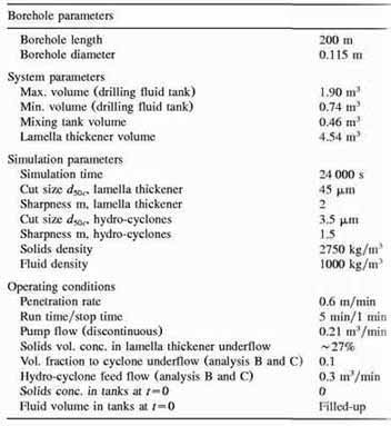
Table 3. Description of simulation run A, B and C
| Simulation A |
Particle separation by the lamella thickener, without the
hydro-cyclones. |
| Simulation B |
Particle separation by the lamella thickener and the hydro-cyclones.
Underflow from the hydro-cyclones are disposed |
| Simulation C |
Particle separation by the lamella thickener and the hydro-cyclones.
Underflow from the hydro-cyclones are fed into the mixing
tank. |
The actual values of the parameters dSOc and m are chosen with respect to
field data (Fig. 10) and calculations according to Eqs. (6)-(9). R is adjusted
individually in each of the following simulations but is close to 0.1. The
reason is that the experience based amount of ~50% w/w solids in the underflow
should be fulfilled. The value for the overflow and underflow are calculated by
equations Eqs. (10) and (11):
q0 = q(1-R) (10)
qu = qR (11)
where index
o and u denote overflow and underflow, respectively. Particle size distribution
curves are calculated by:
 (12)
(12)
 (13)
(13)
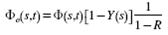
where Фu(s,t), Ф0(s,t) and Ф(s,t) represent the particle size
distributions in the underflow, overflow and the feed. The terms (1/R) and
(1/1-R) are required for the functions to correctly represent the new
concentration levels together with the new flow rates.
Another detail to
consider is that the volume of the lamella thickener causes a delay of Δt=v/q s
before the incoming slurry flow particles are reported in the overflow or
underflow. This is the case when the flow is laminar and no mixing occurs. The
described model uses a memory buffer to stall the signal Δt s, according to Eq.
(14):
Фout(s,t) = Фin(s,t – Δt) (14)
Фout(s,t) = 0 для t≤Δt (15)
Eq.
(15) implies that the lamella thickener is initially assumed filled with clear
water.
3.4. Hydro-cyclones
Several equations for calculation of the separation efficiency for
hydro-cyclones have been derived during the past decades (Heiskanen, 1993). The
parameters involved are the geometry, operating conditions and fluid
characteristics. One model that is often used is the empirical model given by
Plitt (Wills, 1997):
 (16)
(16)
In this equation Dc =
hydro-cyclone diameter [cm], D0 = overflow diameter [cm], Di = inlet diameter
[cm], φ = volumetric fraction of solids in the feed, Du = underflow diameter
[cm], h = cyclone height [cm], Q = feed volume flow rate [m3/h], ρs = solids
density [g/ cm3] and ρf= fluid density [g/cm3]. The sharpness parameter m is
given as:
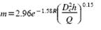 (17)
(17)
By inserting Eq. (16) and Eq. (17) into
the Rosin-Rammler formula Eq. (8) and compensating for the underflow Eq. (9),
the efficiency curve for the hydro-cyclone unit is obtained.
Table 4.Results from numerical simulations
4. Resulting calculations
The described model has been implemented within the Matlab Simulink
math-package and three different simulation runs representing possible system
configurations are presented here. Input parameters and conditions are
described in Tables 2 and 3. Results are presented in Table 4 and Figs. 8 and
9.
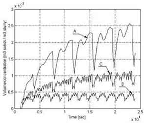
Fig. 8. Results from numerical simulations that
describe the volume concentrations of solids in the flow to the hammer tool.
Curves A, B and C result, respectively, from simulation runs A, B and C.
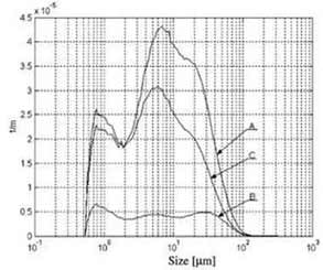
Fig. 9. Results from numerical simulations that describes the
particle size distribution curves at t=24000 s (Fig. 8) in the flow to the
hammer tool. The area under the curves represents the volume concentration of
solids in the flow.
4.1. Results
Important results from the simulations are the total particle volume sent to
the hammer tool and the external water consumption. The reasons are that the
hammer life is intimately related to the presence of abrasive particles in the
flow and that water consumption (and thereby waste flow) must be low for
efficient use of the system. Results presented in Table 4 indicate that the mean
concentration of solids in the feed to the hammer tool is approximately 0.44%
w/w when the lamella thickener is used for particle-fluid separation
(simulation A). Particle flow is reduced by ~ 80% when hydro-cyclones are used
as a complement (simulation B) and the underflow is disposed. When underflow
from the hydro-cyclone unit is re-used (simulation C), the reduction is about
50%. The simulations are valid for the case of no flocculent in the flow. Fig. 8
describes the solids volume concentration curves in the flow to the hammer tool,
during drilling of a 200-m deep borehole. The particle size distribution curves
(for t=24 000 s in Fig. 8) are presented in Fig. 9.
5. Conclusion
Drilling with water driven DTH-hammers is a recently developed method for
competitive production of boreholes. The technology requires large flow rates
of preferably high quality fluid to drive the hammer tool and flush the
borehole. One method to reduce the consumption is to process and recycle the
used drilling fluid. Studies have been performed to find cost-effective suitable
cleaning methods and a mobile prototype unit has been developed. This unit
includes components for both pressurising and cleaning drilling fluid to enable
recycling and thereby efficient drilling.
A process simulation model was also
developed within this project. Simulations determine particle size
distributions, concentrations and flows at strategic locations, whereby the
system configuration can be optimised. Results indicate that particle flows to
the hammer tool is reduced by ~ 80% when hydro-cyclones are used as a complement
to the lamella thickener, and the underflow is disposed. When underflow from the
hydro-cyclone unit is re-used, the reduction is about 50%. The simulations are
valid for the case of no flocculent in the flow.
Practical prototype
experiences and results from numerical simulations will be used in designing
next generation systems, leading to even more cost-effective production with
further increases in the competitiveness of the drilling method.
Acknowledgments
This work was supported by Technology Link Foundation, The Research Council
of Norrbotten and Wassara AB. They are greatly acknowledged.
Appendix A: Field data
The mining company LKAB in Malmberget, Sweden, has during year 2001 produced
several boreholes for safety investigations. The distances from the ground down
to the mine were measured and rock surveillance systems were installed to
monitor movements. The latter is a sign of instability and, therefore, a hazard
for the residents and the surrounding environment. The holes were drilled using
water driven DTH-hammer tools together with the above described prototype
system. Recycling was used during approximately 200 m of drilling, and the
capacity of the lamella thickener was studied. Conditions for this drill work
are presented in Tables 5 and 6. Laboratory results are shown in Table 7 and
Fig. 10.
Table 5. Operating conditions during field experiments
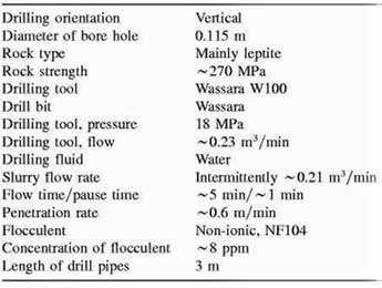
Table 6. Time and positions for samples
| Fluid sample no. |
Position |
Time (min) |
| 1 |
Lamella thickener overflow |
30 |
| 2 |
Lamella thickener overflow |
60 |
| 3 |
Lamella thickener overflow |
90 |
| 4 |
After hammer tool, before addition of flocculent |
0 |
Table 7. Laboratory results from flow samples
| Flow sample number |
Mass fraction solids (%) |
| 1-overflow |
0.05 |
| 2-overflow |
0.10 |
| 3-overflow |
0.05 |
| 4-feed |
8.4 |
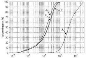
Fig.
10. Laboratory results of particle distributions in fluid samples. Samples 1—3
are taken from the lamella thickener overflow at time 30, 60 and 90 min,
respectively. Curve 4 describes the feed at t=0 and before addition of
flocculent. The flow rate was ~0.21 m3/min.
References
Crowe, C., Sommerfeld, M., Tsuji, Y., 1998. Multiphase Flows With Droplets
and Particles. CRC Press.
Heiskanen, K., 1993. Particle Classification.
Chapman and Hall.
Tuomas G., Nordell B., 2000. Down-Hole Water Driven Hammer
Drilling For BTES Applications. In: Proceedings Terrastock 2000, 8th
International Conference on Thermal Energy Storage. Stuttgart, Germany, pp.
503-508.
Tuomas G., 2001. System for Water-Driven Downhole Hammer Drilling.
In: Proceedings Offshore Technology Conference OTC 2001, April 30 to May 3,
Houston, Texas, USA, pp. 399-407.
Wills, B.A, 1997. Mineral Processing
Technology. Butterworth-Heinemann.
Oderyd, L., 2001. Personal
communication.