Mary Ann Ingram†, Robert Romanofsky*, Richard Q. Lee*, Felix Miranda*, Zoya Popovic?, John Langley§, William C. Barott†, M. Usman Ahmed†, and Dan Mandl‡
†Georgia Institute of Technology, Atlanta, GA 30332-0250,
*NASA GRC,21000 Brookpark Rd, Cleveland OH 44135, ?University of Colorado, Boulder, CO 80309-0425, §Saquish
Group, POB 3554, Half Moon Bay, CA 94019, ‡NASA GSFC, Code 584, Greenbelt, MD 20771
Source of information: http://eo1.gsfc.nasa.gov/new/validationReport/Technology/ SensorWebs/EO-1OptimizingSatelliteCommunications.pdf
Abstract – A new adaptive antenna array architecture for lowearth-orbit satellite ground stations is being investigated. Theseground stations are intended to have no moving parts and couldpotentially be operated in populated areas, where terrestrial interferenceis likely. The architecture includes multiple, moderatelydirective phased arrays. The phased arrays, each steeredin the approximate direction of the satellite, are adaptively combinedto enhance the signal-to-interference-plus-noise (SNIR) ofthe desired satellite. The size of each phased array is to betraded-off with the number of phased arrays, to optimize cost,while meeting a bit-error-rate threshold. Also, two phased arrayarchitectures are being prototyped: a space-fed lens arrayand a reflect-array. If two co-channel satellites are in the fieldof view of the phased arrays, then multiuser detection techniquesmay enable simultaneous demodulation of the satellitesignals, also known as space division multiple access (SDMA).We report on Phase I of the project, in which fixed directionalelements are adaptively combined in a prototype to demodulatethe S-band downlink of the EO-1 satellite.
I. INTRODUCTION
A typical ground station for NASA’s low-earth orbiting
(LEO) satellites utilizes a single large (10 m – 11 m) dish antenna,
and tracks a single satellite at a time by mechanically
scanning the antenna through as much as 160 degrees. The
downlink supports data rates ranging from 2 kbps up to 150
Mbps. To maximize contact with these polar-orbiting but
precessing satellites, the ground stations are near the poles.
The ground stations cost from $2M to $4M each to build and
have an associated high maintenance cost.
The purpose of the project reported here is to determine the
feasibility of a remotely programmable ground station, with
ideally no moving parts, in non-polar regions, and with a cost
goal of less than a tenth of the cost of a current ground station
to build and maintain. Instead of a single dish, the ground
system would comprise a number of phased arrays with
small-to-moderate aperture sizes, and the phased array outputs
would be adaptively combined to maximize the signal-to-interference-and-noise-ratio (SINR) of the desired satellite
transmission. The focus is on the physical layer, that is, the
design of the RF front end and digital signal processing of the
phased array outputs.
Such a future ground station will not support the highest data
rates now possible with a large dish, however, since more of
the ground stations would be deployed, the data could be
downloaded in a distributed manner as the satellite passes
over a series of ground stations. Our vision is that the ground
stations would be connected via the internet, so that any
given LEO satellite can be in nearly continuous communication
with the network on Earth. While the focus of the current
project is for a ground station to communicate with only one
satellite at a time, the architecture being studied is capable of
rapidly and electronically controlled reconfiguration, to enable
fast switching from one satellite to another within the
same constellation or simultaneous communication with multiple
satellites.
Two phased array technologies are being investigated by researchers
at NASA’s Glenn Research Center and at University
of Colorado. One of these, the space-fed lens array, is
composed of a feed array and a radiating array with each corresponding
element pair interconnected by transmission lines
of different lengths to radiate a plane wave in the forward direction.
The other of these, the reflectarray, has a surface
containing integrated phase shifters and patch radiators is illuminated
by a single feed at a virtual focus. The signal
passes through the reflect-mode phase shifters and is reradiated
as a collimated beam in essentially any preferred direction
in the hemisphere in front of the antenna. Both approaches
provide electronic beam steering, have no moving
parts, and promise low cost.
The other part of the project addresses the signal processing of the outputs of the multiple phased arrays, which will be referred to as directional elements (DEs). Ultimately, the jobs of the receiver signal processor are to (1) perform frequency and timing synchronization for each DE, (2) to compute the adaptive weights that will be applied to the DEs before they are summed, (3) demodulate and detect the transmitted symbols, and (4) steer the DEs. The focus of the signal processing efforts in the first year of the project has been on the first three jobs. A four-element prototype was constructed to demonstrate these receiver signal processing functions for the Earth Observing One (EO-1) satellite at S-band. The prototype was demonstrated on the roof of the five-story Georgia Centers for Advanced Telecommunication Technology (GCATT) Building in urban Atlanta, GA. In the remainder of this paper, the two phased array efforts will be discussed, followed by a description of adaptive array demonstration.
II. THE SPACE-FED LENS
Using a discrete lens array (DLA) as the front end of a low
cost adaptive ground antenna system has cost and performance
advantages over conventional reflector or electronically
steered phased array antennas. Steering large reflector rapidly
by mechanical means is difficult due to the inertia and mass
of the antenna which often requires high maintenance costs
resulting from misalignment of moving parts. On the other
hand, large solid-state based phased arrays suffer from excessive
cost and very low efficiency as a result of large power
combining losses in the circuitry for large aperture. Due to
low power efficiency of solid-state power amplifiers and high
insertion losses in the phase shifters, thermal management is
also a big concern as a result of high density integration.
The DLA is space-fed so there are no power combining
losses. Furthermore, beam steering is achieved by switching
between adjacent feeds using pin diode or MESFET switches
instead of phase shifters, which significantly simplifies the
array architecture and thermal management problem. In addition,
small array feeds with amplitude-controlled elements
can be used to provide smooth transitions between “handoff”
beams making beam steering seamlessly.
As illustrated in Fig.1, a DLA is comprised of a feed array and a radiating array with delay line connecting each corresponding pair of elements. For the proposed DLA, the
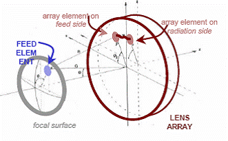
Fig.1 Schematic of a space-fed discrete lens array
focal surface where the feeds are located is 2.5 lo, and the inter-element spacing is 0.5 lo where lo is the free-space wavelength. The design and simulation of the antenna elements and arrays are carried out with Ansoft Designer CAD software. For the feed side array, a 7.3 mm square patch antenna designed for linear polarization at X-band (~8.2 GHz) was selected selected. Its simulated return loss was found to be better than 50 dB with a gain of about 2.8 dB.
The element for the radiating array is a square patch with truncated corners designed for left-hand circular polarization (LHCP) at the same frequency. The simulated axial ratio for the LHCP antenna is 0.13 dB at 0 degrees , and is less than 3 dB over the entire scan of ± 55 degrees; and the simulated gain is 2.1 dB. The simulated results are found to be in good agreements with the patch measured data. Figure 2 shows the interconnect of the unit element where the element on the feed side is connected to the radiating element through vias and striplines of different length to
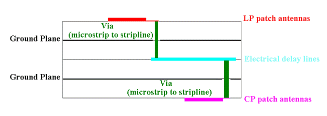
Fig. 2 Unit element and interconnects
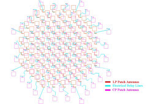
Fig. 3 Layout of the passive DLA
provide proper phase delays for producing a beam in the forward
direction. Fig. 3 shows an AUTOCAD layout of the
passive DLA. Since an active DLA will be designed and implemented
after the passive lens is tested, the passive DLA
layout will be as close to the active array as possible, so the
passive array data can be used for gain/loss calibration of the
active array antenna.
The G/T for the DLA has been calculated and was found to
be strongly dependent on the number and type of LNA. For the 100-element DLA, using 2 LNAs will yield a G/T which
ranges from 8 to 17.3 dB/K, depending on the type of LNA
used. The testing of the 100-element DLA is on going with
measured results to be published in the near future.
III. FERROELECTRIC REFLECTARRAY ANTENNA
A scanning reflectarray consists of a flat surface with diameter
D containing N integrated phase shifters and N patch radiators
that is illuminated by a single feed at a virtual focus
located a distance f from the surface such that f/D l1. The
modulated signal from the feed passes through the N reflectmode
phase shifters and is re-radiated as a focused beam in
essentially any preferred direction in the hemisphere in front
of the antenna, as in a conventional phased array. The control
algorithm is nearly identical to that of a conventional phased
array, the exception being an a priori setting of all phase
shifters to compensate for the spherical wave-front from the
feed. That is, the signal from the feed reaches the central
element of the aperture before it reaches elements toward the
perimeter. Of course the physics insofar as inter-element
spacing, mutual coupling, scan loss, etc. is concerned is the
same as for a conventional directly radiating phased array.
One difficulty with implementing such as array arises from the fact that the phase shifters are necessarily between the feed horn and the patch radiating elements. Hence, they introduce line loss in front of the first stage low noise amplifier (LNA) and cause system noise temperature to escalate. Figure 4 shows calculated noise temperature as a function of phase shifter loss. Secondly, constructing the active array economically can be a challenge. We have devised very low loss phase shifters based on thin ferroelectric films [1-2].
Moreover, the phase shifters require only one bias line and can be built using a simple lithography process since the smallest feature size is on the order of 10 m. Another reason to believe that the reflectarray will have profound cost advantages is attributed to its simple structure. The reflectarray requires only a multilayer DC bias distribution board, a support platen which also serves as the DC and RF ground plane, and the RF layer populated with 2N devices that can be automatically placed and wire bonded. A corrugated or dual-mode feed horn plus the supporting struts, an LNA, and a controller complete the system front end. The X-band phase shifters consist of four cascaded coupled microstrip lines patterned over 400 nm thick laser ablated Ba0.50Sr0.50TiO3 films, followed by a switch. The “ferroelectric” section provides nominally 180 degrees of analog phase shift. As a bias from 0 to 350 V is applied across the coupled line electrodes, the relative dielectric constant of the film tunes from about 2000 to 800, thereby modifying the propagation constant. Note that the ferroelectric films are excellent dielectrics and the current draw is negligible so there is virtually no power consumption. The beam lead Si diode switch toggles between an open and virtual short circuit realized with a quarter-wave radial stub. This results in a digital transition between a reflection coefficient with magnitude near unity and phase of 0 degrees and 180 degrees, respectively.
Thus, a full 2? phase shift is possible. The prototype X-band phase shifters presented in Figures 5 and 6 were idealized in the sense that the virtual short circuit was wire bonded. The diode switch has an insertion loss of about 0.5 dB in the on-state and an isolation of about 15 dB, so actual performance of the phase shifters will degrade by about 0.5 dB. The next step is to iterate the phase shifter design to achieve a full 2 degrees phase shift with an integrated diode to form a true hybrid ferroelectric-semiconductor device meeting the loss target of 2.5 dB.
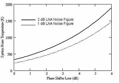
Figure 4. Calculated reflectarray system noise temperature as a function of phase shifter insertion loss. A background temperature of 55 K is assumed.
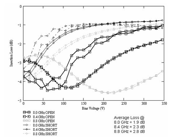
Figure 5. Measured insertion loss of ferroelectric phase shifter at three different X-band frequencies.
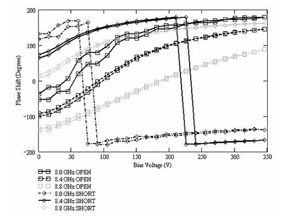
Figure 6. Measured insertion phase of ferroelectric phase shifter at three different X-band frequencies.
IV. ADAPTIVE SIGNAL PROCESSING
A. Introduction
Spatial adaptive processing, or the adaptive combination of multiple receive antennas, generally provides several features: array gain, interference suppression, diversity gain, and multiple-user detection. Array gain is purely a function of the number of elements. If there are N elements with equal average signal-to-noise-ratio (SNR), then the average SNR of the array combiner is 10log10(N) higher in dB than the average SNR of any one of the elements. Interference suppression happens when the adaptive array steers a pattern null in the direction of the interference. In this case, the SNR of the desired signal is not degraded much unless the desired and interference signals arrive at the array from nearly the same direction.
If multiple copies of the same signal arrive from different directions, a condition known as multipath, the SNR of an individual element can drop dramatically if the copies add destructively. This is called a “multipath fade” [3]. Since each directional element (DE) will not have the high directivity of a 10m dish antenna, and because the DEs may be steered to some low elevation angles to maximize the time on the satellite, the DEs may recieve some multipath. Given that the DEs have sufficient spacing, then they are unlikely to fade at the same time. This implies that the SNR at the output of the adaptive combiner is less likely to exhibit fades that are as deep as the fades on individual elements. This difference in depths of fades is the diversity gain. The statistics for diversity gain can be calculated for certain standard types of fading on individual elements, such as Rayleigh, Rician, or Nakagami fading [3].
Finally, multi-user detection (MUD) allows multiple interfering signals to be separated by the adaptive processor [4]. Theoretically, this could happen if multiple satellites within the field of view of the ground station transmitted at the same frequency. MUD is related to interference suppression: as long as the array response vectors of the different satellites are not nearly co-linear, the array signal processor can compute a different weight vector for each satellite. The i-th weight vector suppresses all signals except the signal from the ith satellite.
Two additional signal processing functions are necessary: frequency synchronization and DE steering. Frequency synchronization, or the act of aligning the phase of the received signal’s carrier with the phase of the carrier reference in the receiver, is a necessary pre-requisite to adaptive combining. DE steering keeps the DEs pointed in the direction of the desired satellite. In the first year of the project, a prototype was built to demonstrate adaptive signal processing of four DEs for the 4 kbps BPSK downlink of the EO-1 satellite. Frequency synchronization, array gain and diversity gain were successfully demonstrated. There was no co-channel interference for this particular satellite and channel, so neither interference suppression nor MUD was necessary. Also, in the first year, the DEs were fixed and not scanned. Therefore, DE steering was not necessary.
B. The Front End of the Prototype
The DEs were the helical antennas shown in Figure 7. The buildings in the left background are part of the downtown area of Atlanta, GA. Each element had a 3dB beamwidth of approximately 45°, right hand circular polarization, and a gain of about 11.4dB at 2.27GHz. The urban environment in Atlanta causes a challenge in the design of the RF hardware chain.The primary difficulty is the presence of high power out-of-band signals from PCS, XM, and Sirius Radio. While PCS is located more than 250Mhz from the EO-1 signal, XM and Sirius posed a particular challenge as they are located as close as 50Mhz to EO-1 and are more than 60dBstronger than EO-1. If left unchecked, these interferers create two problems in the receiver system. First, they significantly raise the total power into the down converter and necessitate a higher amount of attenuation prior to down conversion. This is turn raises the effective noise temperature of the system and thus can reduce sensitivity and CNR. Second, the large interferer powers can cause intermodulation distortion, which can be a significant problem for the relatively very weak EO-1 signal. A two-fold approach was taken to driving this interference down. First, a very narrow band and low loss filter was developed to pass only the desired signal while greatly attenuating out of band interferers. Second, high performance amplifiers were located which are tolerant to high power signals and have very low intermodulation products. The final receiver design is shown in Figure 8.A picture of the spectrum analyzer during a pass on 24 November 2003 is shown in Figure 9.
The pedestal in the center of the spectrum is caused by the system noise passing through the narrow band filter. Sirius and XM radio can be seen to the right of the main band, still quite powerful despite filtering. The APCOM receiver downconverted the signal to a 16 MHz intermediate frequency (IF). It has a variable attenuator that was set between 15 and 20dB, depending on the channel. Measured input noise characteristics of the APCOM blocks varied from 3-15dB NF, depending on the channel. The IF signal was then sampled at a 1 MHz rate with 12 bits of precision.
C. Frequency Synchronization
Because of the motion of the satellite, Doppler shifting
caused the carrier frequency to change by about 750Hz to 1
kHz every second.
A coarse frequency synchronization was performed first. The
sampled signal was first decimated by a factor of five. Next,
squaring the signal got rid of the modulation and gave a nice
peak at the carrier frequency. FFTs of length 0.1 or 0.05 seconds
(corresponding to 20k or 10k samples) provided a good
balance between accuracy and tracking ability. Linear interpolation
between the FFT results provided the coarse frequency
estimates. The coarsely compensated signal was
decimated again by a factor of five.
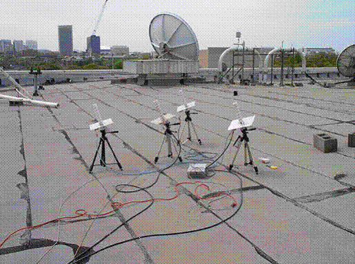
Figure 7. The four helical antennas receiving the 4 kbps downlink from EO-1 on 7 April 2004.
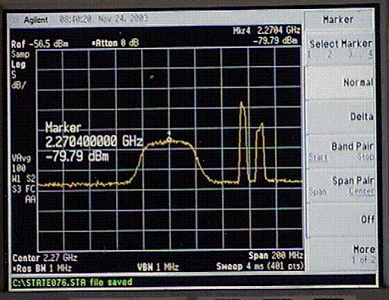
Figure 8. A photo of the spectrum analyzer screen showing the noise pedestal formed by the bandpass filter and the two interference signals Sirius and XM radio.
The horizontal axis is 20 MHz/div, and the vertical axis is 5 dB/div. The signal was passed through a pulse-matched filter that was based on a sinc spectrum truncated to three sidelobes. At this point, there were 10 samples per symbol period. Next, fine frequency adjustments were made. The decision directed PLL was implemented as in [5, pp. 205-221]. The PLL used a second-order loop filter to completely eliminate constant frequency and phase offsets. It did a good job of tracking slowly changing frequency offset as well, as shown by the scatter plot in Figure 9.
This PLL can correct frequency offsets 0.1T, where T is the symbol period. Frequency synchronization was performed separately for each channel. This was found to perform better than perfoming synchronization for one channel and simply applying the resulting correction to all cannels.
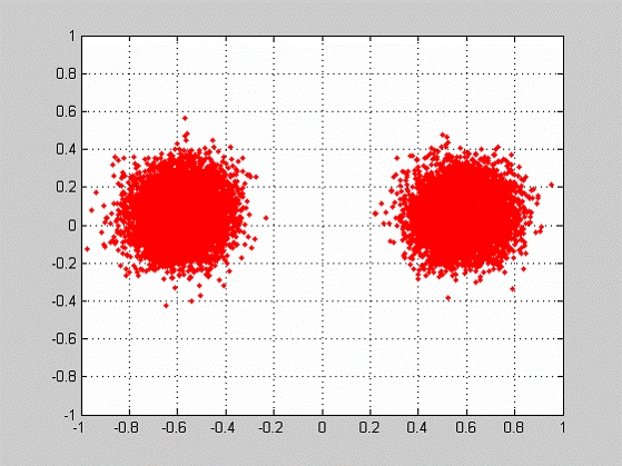
Figure 9. Output of the decision-directed PLL showing a BPSK constellation. The circular symmetry of the clusters indicates Gaussian noise.
D. The Adaptive Combiner
Finally, the outputs of the decision-directed PLL were adaptively weighted and summed. Adaptation is done with a kind of feed-back loop. When a training sequence is available, an error signal may be formed by subtracting the output of the combiner from the ideal version of the signal based on the training signal. In the case of EO-1 4 kbps S-band, the 64 bit BPSK synch mark may be used as the training signal. The adaptive algorithm iteratively adjusts the weights to drive the error to zero. When the average power of the error is minimized, the algorithm is said to have converged. Two well known adaptive algorithms were tried with the prototype: the recursive least squares (RLS) algorithm, and the least mean squares (LMS) algorithm [6]. LMS has the advantage of low complexity and the disadvantage of being slow to converge relative to the other types of algorithms. RLS has the advantage of faster convergence and the disadvantage of higher complexity.
In the 7 April 2004 pass, the results were as follows. The channels had the following average SNRs at the top of the pass: 23.6 dB, 20.3 dB, 19.4 dB, and 14.1 dB. The disparities of the first three were mainly because of the varying noise figures of the APCOM receivers. The fourth APCOM was being repaired at the time, so a lower-performing front end was substituted. The average SNR of the adaptive combiner was 27.3 dB, for both RLS and LMS. When the channel SNRs are unequal, the optimum combiner output average SNR, in the absence of interference, is simply the sum of the input SNRs; this is called maximal ratio combining (MRC). With these input SNRs, the MRC output SNR should be 26.5 dB. The fact that the actual output SNR was almost 1 dB better suggests that some interference suppression was happening. To demonstrate diversity gain, a second pass was conducted on 30 April 2004. This time, instead of the elements being out in the open, they were enclosed in an approximately 30’ by 30’ walled area, with no ceiling, on the roof of the GCATT Bldg. The walls were made of masonry material.
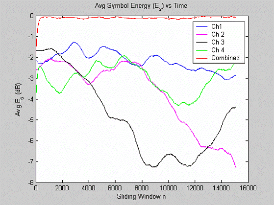
This environment was ideal for intentionally creating multipath, because the signals from the 65 degree elevation pass would reflect from the walls. The configuration of the elements was similar to that in Figure 7, but with a larger spacing of about 6 to 8 feet. In this set of results, the fourth channel had the repaired APCOM receiver. The results are plotted in terms of signal power in dB versus symbol index in Figure 10. The lower four curves are the powers of the four channels. Their fluctuation with time indicates multipath fading. The curve at the very top is the combiner output. Its fades are very slight, compared to the fades of the elements, clearly showing the diversity gain effect.
V. FINANCIAL MODEL
An interactive Excel-based financial modeling tool is being developed. Its purpose is to model the acquisition cost of a next-generation ground station employing adaptive array technology. The model will support present and future generations of satellite downlinks at S, X, and Ka-bands with data rates up to 150 Mbps. The cost model will be updated for the small dish, space-fed lens and reflectarray designs as actual cost data becomes available. By employing Excel’s “Scenarios” feature, multiple pairings of satellite, such as ST- 5, SAC-C, and Aura, with element technology can be quickly evaluated. A link budget is used to determine how many elements are required to meet system performance requirements.
This number, together with cost estimates of the elements, array interface, data processor, power supply, etc. enable a system cost estimate to be computed.Figure 12. Signal powers in dB of each channel and of the adaptive combiner, under intentional multipath conditions, illustrating array and diversity gain.
VI. PLANS FOR THE X-BAND PROTOTYPE
In the second year of the prototyping effort, an X-band prototype will be constructed.The proposed satellite is the SACC, which travels in the same constellation as EO-1. It was chosen because among X-band options, it has a relatively low data rate of 6.06 Mbps and an (assumed) occupied bandwidth of 24 MHz, which can be accommodated by the Georgia Tech data acquisition system. Any higher bandwidth cannot be accommodated. Another change from the first year prototype is that the elements will be steered. Dish antennas are planned, although the GRC phased arrays can be used if they are ready. A preliminary link budget analysis indicates that an element gain of 37 dB will be necessary for an assumed channel noise temperature of 150K, implying a G/T of 15 dB/K.
VII. CONCLUSION
Research and development of adaptive array technology for the ground stations for low-earth orbit satellites is being conducted. Successful adaptive combining was demonstrated on the EO-1 4 kbps BPSK signal using four fixed directional elements. Advances in two types of X-band phased arrays were achieved concurrently, including the creation of a 100-element prototype space-fed lens and a record low-loss phase shifter for the reflectarray. It is hoped that either type of phased can be used as the directional element in the adaptive combiner. The result will be a ground station that should provide extreme flexibility in connecting LEOs with the earth network, as well as one that has no moving parts and a cost that is an fraction of the cost of today’s ground stations.
AKNOWLEDGEMENTS
The authors appreciate the technical support provided by Mr.
Nathan Jones of theGeorgia Tech Research Institute and the
advice of Professor Paul Steffes of the Georgia Tech School
of Electrical and Computer Engineering. The authors gratefully
acknowledge the NASA Earth Science Technology Office
(ESTO) for providing the funding to conduct this research.
REFERENCES
1. R. R. Romanofsky and A. H. Qureshi, “A Model for Ferroelectric Phase Shifters,” IEEE Trans. Magn., Vol. 36, Sept. 2000, pp. 3491-3494.
2. R. R. Romanofsky, et al., “Analysis and Optimization of Thin Film Ferroelectric Phase Shifters,” Mat. Res. Soc. Symp. Proc. Vol. 603, 2000, pp. 3-14.
3. T. S. Rappaport, Wireless Communications: Principles & Practice. New Jersey:Prentice Hall, 1996.
4. Sergio Verdu, Multiuser Detection, Cambridge University Press, 1998.
5. G. Karam, F. Daffara, and H. Sari, “Simplified Versions of the Maximum-Likelihood Frequency Detector”, Conf. Rec. GLOBECOM’92, Orlando, FL, Dec. 6-9, 1992, paper 11.02.
6. Simon Haykin, Adaptive Filter Theory, 2nd ed., Prentice Hall, Englewood Cliffs, NJ, 1991.