A Model-Based Methodology for Real-Time Verification and Optimization of UHF RFID Systems
Vojtech Derbek, Christian Steger, Reinhold Weiss
Источник: Institute of Technical Informatics, Graz University of Technology, Austria
http://www.eurasip.org/Proceedings/Ext/RFID2007/pdf/s4p1.pdf
Abstract — Nowadays, UHF RFID performance gains on increased importance as tags, readers, protocols and applications are addressed no longer as separated devices, but rather as a system. Resources of transponders are limited in size and available power, which is retrieved from the electric field generated by interrogator’s antenna. This power is restricted by national regulations. As UHF RFID systems have found their major application in highly inhomogeneous field environments of logistic processes, operating setups have critical influence on the performance of the system. This work proposes a methodology for optimization and real-time verification of UHF RFID systems. The novel method allows for considerations for operating setups in the design flow of components and brings a technique for verification of the system in application specific conditions. This technique is based on simulating models in real-time. The proposed methodology closes the gap between design of components and optimization of real-world setups in which the components operate.
I. Introduction
Compared to low-frequency systems, higher performances of UHF RFID systems imply higher costs and more complex design. Here, computer simulation is fundamental. Methodologies for simulation of general analog RF transmitter and receiver systems building on behavioral models have been presented in several works. Khouri et.al. proposed a methodology for verification of wireless system design using HDL behavioral models [9]. The models were further adapted for the simulation of UHF RFID communication links. Boyle et.al. [3] showed that performance evaluation of a wireless digital protocol might lead to misleading results when not considering RF field propagation. Research groups at the University of California, Los Angeles [10] joint their efforts to develop a test bed for wireless communication systems in which for every layer starting with physical devices and ending with transport protocols the impact of technology on the application level performance is evaluated. Here, a combination of physical devices communicating with simulated hardware is used. Such approaches are too computationally expensive to address system and application levels requirements in low level designs. At the same time they do not bring a possibility for direct verification of models in real-time applications.
II. A Model-based Methodology
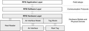
This work proposes a methodology for simulation and realtime verification of UHF RFID systems introducing a multilayer approach. The methodology is based on a modeling framework depicted in figure 1. The model is abstracted into three layers: (i) an RFID hardware layer, (ii) an RFID software layer, and (iii) an RFID application layer. The RFID hardware layer includes models of UHF RFID hardware components with three main independent and exchangeable modules for a reader, a tag, and an air interface. The RFID software layer introduces aspects of protocols and data communication into the simulation and verification flow. The RFID application layer provides a set of field setup parameters and configurations. It specifies the UHF RFID environmental operating conditions for the other two layers, for example warehouse or library environments, antenna and read points arrangements.

Fig. 1. Layers of a framework for UHF RFID system modeling.
The proposed methodology is focused on the verification of hardware component designs and system and application setup optimizations based on a model of UHF RFID systems within defined margins of granularity of detail. Known limits of the UHF RFID design space are applied on methodologies used by general modeling and simulation tools. This limits the complexity of the task and yields simulations with access to multiple abstraction levels.
The implementation of this methodology comprises two platforms as depicted in figure 2: (i) a simulation platform and (ii) a real-time verification platform. The verification and optimization procedure is based on models of an UHF RFID system [5], [6]. Individual components are first modeled, simulated and verified separately using traditional design methods in the simulation platform. Afterwards, a multi-layer
simulation is deployed in order to optimize system parameters. Finally the models can be updated or their structure can be modified. Models of system components that have passed the initial design verification and optimization process in the simulation test bench are transferred to the real-time verification platform. By applying HW-SW co-design methodologies the models are mapped and synthesized or compiled for a hardware platform. Hardware-in-the-Loop (HIL) simulation based on FPGA and DSP [4], [7] was introduced into the proposed architecture to enable real-time verification of models in their target environments. Using this technique the synthesized model of the device-under-development is configured and set up for verification in a target operating environment. The verification is performed in real-time against real-world stimuli. The test bed consists of commercially available UHF RFID devices, reference devices and measurement equipment. The measured results are fed back into the model and further used to define parameters margins for the system optimization in the simulation platform.

Fig. 2. Methodology for model-based real-time verification of UHF RFID system. A single module can be a model of an UHF RFID device or an air
interface model.
To enable the exchangeability of the three main modules of the hardware layer, their interfaces are formally defined at the behavioral level of the model. The modules themselves can then be implemented at various levels of abstraction, complexity, and granularity of detail. The multi-layer simulation of the entire system starts with simulations first performed at each level individually. To configure the software layer models a set of parameters is extracted from simulations of underlying hardware platform. Once the set of parameters and their values is known, these are applied to the simulation of the software layer models. Finally the set of test parameters is extended by values of operating environment settings for application layer simulations.
III. Implementation of Platforms
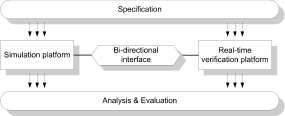
The modeling and simulation framework of the proposed methodology was implemented for UHF RFID technology with passive transponders and single or two reader environments. Figure 3 shows the proposed system level design flow. It starts in the first step with the specification. In the second steps it applies the proposed methodology and ends with the analysis and evaluation of the system. The simulation platform and real-time verification platform interact with each other through a bi-directional interface in discrete times during the model-based optimization and verification procedure.

Fig. 3. System level design flow based on the proposed methodology
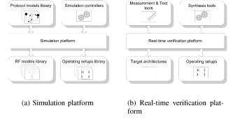
Components of the implemented platforms are shown in figure 4. The simulation platform comprises libraries and simulation controllers. The libraries are defined for each layer of the framework. The RF model library is assigned to the RFID hardware layer. It defines models of analog components of the system. The protocol model library is assigned to the RFID software layer. It defines the implementations of reader and tag statemachines for various communication protocols. Operating setups library is assigned to the RFID application layer and defines physical setups of UHF RFID systems, positioning, antenna switching patterns, tag movement scenarios, etc. The real-time verification platform comprises target architectures for real-time execution of models and synthesis tools assigned to them. Measurement and test tools were integrated into the flow of the system verification procedure. The platform furthermore embodies physical operating setups including physical hardware.
IV. Environments for Implementation of Simulation Platform
The simulation platform was implemented based on models developed in the Matlab Simulink® environment. The models handle analog and digital designs of the UHF RFID system. The real-time verification platform was implemented primarily for the verification of designs of digital subsystems of UHF RFID system with a limited possibility to verify analog designs. The implementation environment furthermore allows for simulation of heterogeneous models in various languages. C++ based models are linked to Simulink® through S-functions. VHDL models are executed within a cosimulation environment [8] implemented in the SyAD® tool.

Fig. 4. Components of implementation of the proposed methodology
A. Model for the Simulation of an UHF RFID System
The model gives an insight into the behavior of the analog and digital structures of the UHF RFID system in terms of providing envelope signals of power transmitted by the reader, power received by the tag, backscatter signal, tag ASIC DC voltage level over time and many other. The main modules of the system include models of a reader and tags and a model of the communication channel between the reader and each tag. Simulation of the model provides a time domain analysis of an ASK system. Configurable modules allow exchanging individual blocks to analyze the system performance under various designs and parameter sets and setup conditions. This includes for example modulation filter type, modulation depth, minimum DC voltage level threshold of the ASIC, size of the tag DC voltage buffer capacitor, structure of tag internal circuitry, etc. Details of the reader and tag models are accessible through the hierarchical structure of the model. Behavioral models of the tag are intended to verify and optimize the performance of the system based on functional- and system-level specifications of the design of the physical devices.
Models of radio frequency parts of the UHF RFID system were implemented on the RFID hardware layer of the applied framework. Details about the implementation of the RF parts can be found in [5], [6]. Digital communication protocol is defined on the RFID software layer of the applied framework. For the implementation on this layer is the UHF RFID system model made of two parts: (i) a time-discrete model of a reader, and (ii) a time-discrete model of a tag. The model was implemented in three environments - Simulink®, C++, and VHDL.
B. Architecture for Real-time Simulation of UHF RFID Tag
To verify the digital model in a real environment, a HIL simulation of an UHF RFID tag was implemented. The internal processing of the tag represented by the time-discrete model is simulated while the RF unit represented by the time-continuous model is implemented in hardware and is used for communicating with a physical UHF RFID reader. This model sends data to the reader using a small tag emulator,
which consists of a matching network, an energy store unit and a modulating transistor.
Figure 5 describes the modular concept of the real-time simulation unit. The whole system is split into two main parts, one is called Signal Acquisition Unit (1) and the other is called Tag Simulation Unit (2). To retrieve information from the air interface an RF Sensor Module is used, which is attached to the Signal Optimizer Board preparing the data for processing. The Tag Simulation Unit implements the baseband processing module of the tag.

Fig. 5. Modular structure of the real-time simulation unit
V. Evaluation
The proposed methodology has been evaluated in three phases. First, models of individual layers have been independently verified in simulations against real-world parameters. Second, modules have been developed in hardware and verified in operating scenarios by applying real-time simulation. Third, the complete methodology has been used for performance evaluations and optimizations of UHF RFID setups in several business cases.
A. Simulation Platform
A simulation of a population of over 60 tags moving through a RFID portal setup was used to evaluate the methodology. Results were then compared with measurements in a real operaing setup. The simulation provides only a slightly better results comparing to the measured data, mainly due to higher compactness of the simulated field. The average measured inventory reliability was 98.5% meaning that approximately one tag was missed out of the complete population of 62 tags. The simulated inventory reliability was 96.8% meaning that approximately two tags were missed out of the whole population. Missed tags are an unwanted effect, which is very costly in industrial applications of RFID. Main reasons for missing a tag are that it is not supplied with sufficient power (due to shielding, detuning, etc.) to identify itself or a communication jam due to collisions, which does not let the tag identify itself during its power-on time. While the RF effects on tag performance degradation can be only hardly controlled, the throughput of the system can be influenced significantly by choosing the right set of parameters. Therefore, the above
|
Set 1 |
Set 2 |
|
|
Number of tags in simulation |
62 |
62 |
|
Session |
S0 |
S2 |
|
First tag detected |
1232 ms |
1232 ms |
|
Last tag detected |
4167 ms |
3667 ms |
|
Total number of detections |
448 |
60 |
|
Number of different tags detected |
60 |
60 |
|
Anticollision rate |
130.984 tags/s |
24.6371 tags/s |
Table 1. Summary of system performance under different protocol settings
|
System |
LE |
Comment |
|
|
Cyclone II 2C35 |
33216 |
100 % |
Reference FPGA chip |
|
Nios II/f |
1800-2000 |
(5%) |
Nios II processor core |
|
Tag HW |
1469 |
4% |
Singe Tag HW (Receiver, Transmitter) |
|
Multi Tag System |
approx. 8000 |
25% |
SOPC with 4 tag hardware units |
Table 2. Chip area utilization
described scenario was first simulated with the protocol setting using Session 0 implementing no persistence time(Set 1). In the second case (Set 2), the protocol was set to Session 2, which implements a specified persistence time. The results are summarized in table 1. Time of the interrogation round is reduced by 13.9% for Set 2 comparing to Set 1 due to avoiding unnecessary repetetive participation of tags in the identification process.
B. Real-time Simulation of Multiple Tags Using FPGA
Applying multiple tags in the reader field provides vital information for the evaluation of the quality of the collision arbitration. To simulate multiple RFID tags on one hardware simulator time critical functions of the protocol were parallelized. A hardware software codesign architecture for model based development of UHF RFID prototypes based on a FPGA platform wad developed to solve the problem [4]. The major characteristic are:
• The design supports high level languages.
• Prototype implementation using HW-SW codesign flow is based on automatically synthesizable models.
• One model is used both for software simulation and for real-time verification in hardware.
• Model partitioning is optimized for UHF RFID specifics.
The design work flow is based on commercially available Quartus II [2] software and Cyclone II [1] hardware tool chain by Altera®. The platform achieves to emulate multiple Matlab Simulink® models of RFID tags on a single FPGA board. The design implements time critical RFID functions as hardware units. These run parallel for every simulated RFID tag. The hardware software codesign of the proposed RFID tag model is implemented in Matlab Simulink®. The HDL code of these parts is generated automatically. Software parts are based on a C++ model and they are implemented on the Altera Nios II soft core processor. The table 2 summarizes the chip area utilization. This architecture is capable of executing multiple tag models within time constraints that are given by the communication protocol.
VI. Conclusion
This paper presented a methodology for verification and optimization of UHF RFID systems. The methodology is based on simulation of models of UHF RFID systems and their real-time verification in application specific conditions. The gap between design of components and optimization of setups in real operating environments has been closed. Future work will involve interfacing of the UHF RFID model with RF field simulation tools.
References
[1] Altera. Cyclone II Device
http://www.altera.com/literature/hb/cyc2/cyc2 cii5v1.pdf.
[2] Altera. Quartus II Development Software Handbook v6.0.
http://www.altera.com/literature/hb/qts/quartusii handbook. pdf.
[3] S. Boyle, D. McKeon, R.A. Meyer, and B. Ollerton. Network simulation of the electronic battlefield. Users Group Conference, 2004. Proceedings, 2005.
[4] Vojtech Derbek, Florian Plank, Christian Steger, Josef Preishuber-Pfluegl, and Markus Pistauer. Simulation and modeling platform for real-time UHF RFID tag design verification and testing. Proceedings of the IEEE International Conference on System, Signals and Devices, Hammamet, Tunisia, March 2007.
[5] Vojtech Derbek, Christian Steger, Suad Kajtazovic, Josef Preishuber-Pfluegl, and Markus Pistauer. Model of UHF RFID tag for system and application level simulation. Proceedings of IEEE International Behavioral Modeling and Simulation Workshop, San Jose, CA, USA, September 2005.
[6] Vojtech Derbek, Christian Steger, Josef Preishuber-Pfluegl, and Markus Pistauer. Architecture for model-based UHF RFID system design verification. Proceedings of the European Conference on Circuit Theory and Design, Cork, Ireland, August 2005.
[7] Vojtech Derbek, Daniel Wischounig, Christian Steger, Josef Preishuber-Pfluegl, and Markus Pistauer. Simulation Platform for UHF RFID. Proceedings of Conference on Design Automation and Test in Europe (DATE), Nice, France, April 2007.
[8] S. Kajtazovic, M. Pistauer, and C. Steger. A HDL-independent modeling methodology for heterogeneous system designs. Behavioral Modeling and Simulation Workshop, 2005. BMAS 2005. Proceedings of the 2005 IEEE International.
[9] Rami Khouri, Vincent Beroulle, Tan-Phu Vuong, and Smail Tedjini. Wireless system design optimization using a VHDL-AMS behavioral model of the RF link: Radio-Frequency Identification case study. Joint SoC-EUSAI conference, October 2005. [10] M. Takai, R. Bagrodia, M. Gerla, B. Daneshrad, M. Fitz, M.S.E. Belding-Royer, S. Krishnamurthy, M. Molle, P. Mohapatra, R. Rao, U. Mitra, C.-C. Shen, and J. Evans. Scalable Test Bed for Next-Generation Wireless Networking Technologies. Proceedings of First International Conference on Testbeds and Research Infrastructures for the Development of Networks and Communities, 2005.