Screened and Shielded Cabling - Noise Immunity, Grounding, and the Antenna Myth
Fundamentals of Noise Interference
Valerie Rybinski
Электронный вариант статьи: http://www.siemon.com/us/standards/Screened and Shielded Guide 3 Fundamentals of Noise Interference.asp
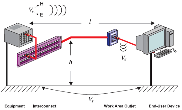
All applications require positive signal-to-noise (SNR) margins to transmit within allocated bit error rate (BER) levels. This means that the data signal being transmitted must be of greater magnitude than all of the combined noise disturbers coupled onto the transmission line (i.e. the structured cabling). As shown in figure 2, noise can be coupled onto twisted-pair cabling in any or all of three ways:
- Differential noise (Vd): Noise induced from an adjacent twisted-pair or balanced cable
- Environmental noise (Ve): Noise induced by an external electromagnetic field
- Ground loop noise (Vg): Noise induced by a difference in potential between conductor ends

Figure 1. LAN Noise Sources
Different applications have varying sensitivity to interference from these noise sources depending upon their capabilities. For example, the 10GBASE-T application is commonly recognized to be extremely sensitive to alien crosstalk (differential mode cable-to-cable coupling) because its digital signal processing (DSP) capability electronically cancels internal pair-to-pair crosstalk within each channel. Unlike pair-to-pair crosstalk, alien crosstalk cannot be cancelled by DSP. Conversely, since the magnitude of alien crosstalk is very small compared to the magnitude of pair-to-pair crosstalk, the presence of alien crosstalk minimally impacts the performance of other applications, such as 100BASE-T and 1000BASE-T that employ partial or no crosstalk cancelling algorithms.
Electromagnetic compatibility (EMC) describes both a system's susceptibility to interference from (immunity) and potential to disturb (emissions) outside sources and is an important indicator of a system's ability to co-exist with other electronic/electrical devices. Noise immunity and emissions performance is reciprocal, meaning that the cabling system's ability to maintain immunity to interference is proportional to the system's potential to radiate. Interestingly, while much unnecessary emphasis is placed on immunity considerations, it is an understood fact that structured cabling systems do not radiate or interfere with other equipment or systems in the telecommunications environment!
Differential noise disturbers: Alien crosstalk and internal pair-to-pair crosstalk are examples of differential mode noise disturbers that must be minimized through proper cabling system design. Susceptibility to interference from differential mode sources is dependent upon system balance and can be improved by isolating or separating conductors that are interfering with each other. Cabling with improved balance (i.e. category 6 and above) exhibits better internal crosstalk and alien crosstalk performance. Since no cable is perfectly balanced, strategies such as using dielectric material to separate conductors or using metal foil to isolate conductors are used to further improve crosstalk performance. For example, category 6A F/UTP cabling is proven to have substantially superior alien crosstalk performance than category 6A UTP cabling because its overall foil construction reduces alien crosstalk coupling to virtually zero. Category 7 S/FTP is proven to have substantially superior pair-to-pair and alien crosstalk performance than any category 6A cabling design because its individual foiled twisted-pair construction reduces pair-to-pair and alien crosstalk coupling to virtually zero. These superior crosstalk levels could not be achieved solely through compliant balance performance.
Environmental noise disturbers: Environmental noise is electromagnetic noise that is comprised of magnetic fields (H) generated by inductive coupling (expressed in A/m) and electric fields (E) generated by capacitive coupling (expressed in V/m). Magnetic field coupling occurs at low frequencies (i.e. 50Hz or 60 Hz) where the balance of the cabling system is more than sufficient to ensure immunity, which means that its impact can be ignored for all types of balanced cabling. Electric fields, however, can produce common mode voltages on balanced cables depending on their frequency. The magnitude of the voltage induced can be modeled assuming that the cabling system is susceptible to interference in the same manner as a loop antenna [1]. For ease of analysis, equation (1) represents a simplified loop antenna model that is appropriate for evaluating the impact on the electric field generated due to various interfering noise source bandwidths as well as the distance relationship of the twisted-pairs to the ground plane. Note that a more detailed model, which specially includes the incidence angle of the electric fields, is required to accurately calculate actual coupled noise voltage.

Where:  is the wavelength of the interfering noise source
- A = the area of the loop formed by the disturbed length of the cabling conductor (l) suspended an average height (h) above the ground plane
- E = the electric field intensity of the interfering source
The wavelength,  , of the interfering source can range anywhere from 500,000m for a 60 Hz signal to shorter than 1m for
RF signals in the 100 MHz and higher band. The electric field strength density varies depending upon the disturber, is
dependent upon proximity to the source, and is normally reduced to null levels at a distance of .3m from the source.
The equation demonstrates that a 60 Hz signal results in an electric field disturbance that can only be measured in the
thousandths of mV range, while sources operating in the MHz range can generate a fairly large electric field disturbance.
For reference, 3V/m is considered to be a reasonable approximation of the average electric field present in a light industrial/
commercial environment and 10V/m is considered to be a reasonable approximation of the average electric field present
in an industrial environment.
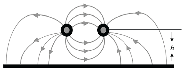
The one variable that impacts the magnitude of the voltage coupled by the electric field is the loop area, A, that is calculated by multiplying the disturbed length of the cabling (l) by the average height (h) from the ground plane. The cross-sectional view in figure 3 depicts the common mode currents that are generated by an electric field. It is these currents that induce unwanted signals on the outermost conductive element of the cabling (i.e. the conductors themselves in a UTP environment or the overall screen/shield in a screened/fully-shielded environment). What becomes readily apparent is that the common mode impedance, as determined by the distance (h) to the ground plane, is not very well controlled in UTP environments. This impedance is dependent upon factors such as distance from metallic raceways, metallic structures surrounding the pairs, the use of non-metallic raceways, and termination location. Conversely, this common mode impedance is well defined and controlled in screened/fully-shielded cabling environments since the screen and/or shield acts as the ground plane. Average approximations for (h) can range anywhere from 0.1 to 1 meter for UTP cabling, but are significantly more constrained (i.e. less than 0.001m) for screened and fully-shielded cabling. This means that screened and fully-shielded cabling theoretically offers 100 to 1,000 times the immunity protection from electric field disturbances than UTP cabling does!

Figure 3. Common Mode Currents
It is important to remember that the overall susceptibility of twisted-pair cables to electric field disturbance is dependent upon both the balance performance of the cabling and the presence of a screen or shield. Well balanced (i.e. category 6 and above) cables should be immune to electromagnetic interference up to 30 MHz. The presence of a shield or screen is necessary to avoid electromagnetic interference at higher frequencies, which is an especially critical consideration for next generation applications. For example, it is reasonable to model that an emerging application using DSP techniques will require a minimum SNR of 20 dB at 100MHz. Since the minimum isolation yielded by balance alone is also 20 dB at 100 MHz, the addition of a screen or shield is necessary to ensure that this application has sufficient noise immunity headroom for operation.
Bibliography: [1] B. Lord, P. Kish, and J. Walling, Nordx/CDT, "Balance Measurements of UTP Connecting Hardware", 1996
^ В начало страницы ^