VFD system description
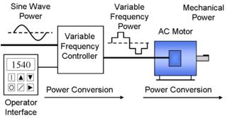
Figure 1 - VFD system
A variable frequency drive system generally consists of an AC motor, a controller and an operator interface.
[1][2]
VFD motor
The motor used in a VFD system is usually a three-phase induction motor. Some types of single-phase motors can be used, but three-phase motors are usually preferred. Various types of synchronous motors offer advantages in some situations, but induction motors are suitable for most purposes and are generally the most economical choice. Motors that are designed for fixed-speed operation are often used. Certain enhancements to the standard motor designs offer higher reliability and better VFD performance, such as MG-31 rated motors.[3]
VFD controller
Variable frequency drive controllers are solid state electronic power conversion devices. The usual design first converts AC input power to DC intermediate power using a rectifier or converter bridge. The rectifier is usually a three-phase, full-wave-diode bridge.
The DC intermediate power is then converted to quasi-sinusoidal AC power using an inverter switching circuit. The inverter circuit is probably the most important section of the VFD, changing DC energy into three channels of AC energy that can be used by an AC motor. These units provide improved power factor, less harmonic distortion, and low sensitivity to the incoming phase sequencing than older phase controlled converter VFD's. Since incoming power is converted to DC, many units will accept single-phase as well as three-phase input power (acting as a phase converter as well as a speed controller); however the unit must be derated when using single phase input as only part of the rectifier bridge is carrying the connected load.[4]
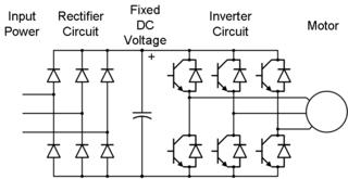
Figure 2 - PWM VFD Diagram
As new types of semiconductor switches have been introduced, these have promptly been applied to inverter circuits at all voltage and current ratings for which suitable devices are available. Introduced in the 1980s, the insulated-gate bipolar transistor (IGBT) became the device used in most VFD inverter circuits in the first decade of the 21st century.
[5] [6] [7]
AC motor characteristics require the applied voltage to be proportionally adjusted whenever the frequency is changed in order to deliver the rated torque. For example, if a motor is designed to operate at 460 volts at 60 Hz, the applied voltage must be reduced to 230 volts when the frequency is reduced to 30 Hz. Thus the ratio of volts per hertz must be regulated to a constant value (460/60 = 7.67 V/Hz in this case). For optimum performance, some further voltage adjustment may be necessary especially at low speeds, but constant volts per hertz is the general rule. This ratio can be changed in order to change the torque delivered by the motor.
[8]
In addition to this simple volts per hertz control more advanced control methods such as vector control and direct torque control (DTC) exist. These methods adjust the motor voltage in such a way that the magnetic flux and mechanical torque of the motor can be precisely controlled.
The usual method used to achieve variable motor voltage is pulse-width modulation (PWM). With PWM voltage control, the inverter switches are used to construct a quasi-sinusoidal output waveform by a series of narrow voltage pulses with pseudosinusoidal varying pulse durations.[9][5]
Operation of the motors above rated name plate speed (base speed) is possible, but is limited to conditions that do not require more power than nameplate rating of the motor. This is sometimes called "field weakening"; and, for AC motors, means operating at less than rated volts/hertz and above rated name plate speed. Permanent magnet synchronous motors have quite limited field weakening speed range due to the constant magnet flux linkage. Naturally the mechanical strength of the rotor and lifetime of the bearings is also limiting the maximum speed of the motor. It is recommended to consult the motor manufacturer if more than 150 % speed is required by the application.
An embedded microprocessor governs the overall operation of the VFD controller. The main microprocessor programming is in firmware that is inaccessible to the VFD user. However, some degree of configuration programming and parameter adjustment is usually provided so that the user can customize the VFD controller to suit specific motor and driven equipment requirements.[5]
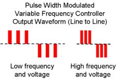
Figure 3 - PWM VFD Output Voltage Waveform